Method and system for recognizing abnormal particles and cell analyzer thereof

A particle and abnormal technology, applied in the field of a method and system for identifying abnormal particles and its cell analyzer, can solve problems such as interference with cell counting, achieve accurate information support, and improve accuracy

Active Publication Date: 2015-04-15
SHENZHEN MINDRAY BIO MEDICAL ELECTRONICS CO LTD +1
View PDF9 Cites 7 Cited by
  • Summary
  • Abstract
  • Description
  • Claims
  • Application Information

AI Technical Summary

Problems solved by technology

[0005] In addition, when using the flow laser scattering method for counting and dete...

Method used


Image

  • Method and system for recognizing abnormal particles and cell analyzer thereof
  • Method and system for recognizing abnormal particles and cell analyzer thereof
  • Method and system for recognizing abnormal particles and cell analyzer thereof

Examples


Embodiment 1

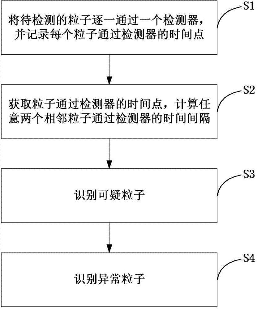
[0033] like image 3 As shown, the embodiment of the present invention provides a method for identifying abnormal particles, which specifically includes the following steps:

[0034] S1. Pass the particles to be detected through a detector one by one, and record the time point when each particle passes the detector; in the embodiment of the present invention, assuming that the detector detects a total of N+1 particles, each particle passes the detection The time point of the device is respectively T 1 ,T 2 ,...,T N+1 .

[0035] S2. Obtain the time point when the particle passes the detector, and calculate the time interval between any two adjacent particles passing the detector:

[0036] d i =T i+1 -T i , i=1, 2, ..., N;

[0037] Among them, T i is the time point when the i-th particle passes the detector, T i+1 is the time point when the i+1th particle passes the detector, d i is the time interval between the i-th particle and the i+1-th particle passing through th...

Embodiment 2

[0049] like Figure 4 As shown, the embodiment of the present invention is improved on the basis of the first embodiment. Specifically, in addition to the steps S1 to S4 described in the first embodiment, the embodiment of the present invention also includes subsequent steps:

[0050] S5. Alarm: When the ratio of the number of abnormal particles to the total number of particles exceeds a set value, the corresponding particle measurement result is regarded as interference, a prompt is output, and an alarm is issued. For example, an alarm device outputs an alarm signal, or displays alarm information on a human-computer interaction interface.

[0051] Wherein, there are many methods for determining the set value, and embodiments of the present invention provide the following methods to determine the set value:

[0052] Method 1: first randomly select a number of normal samples, and count the ratio of the number of abnormal particles to the total number of particles; then randoml...

Embodiment 3

[0057] like Figure 5 As shown, the embodiment of the present invention is improved on the basis of the first embodiment. Specifically, in addition to the steps S1 to S4 described in the first embodiment, the embodiment of the present invention also includes subsequent steps:

[0058] S5. Excluding abnormal particles. Specifically, the embodiment of the present invention provides two ways to exclude abnormal particles. Wherein, the first way is to ignore the abnormal particles in the subsequent statistics and analysis, for example, delete the points corresponding to the abnormal particles from the scatter diagram and so on. The second method is to subtract the number of abnormal particles from the total number of particles, and the result obtained is the actual total number of particles after excluding abnormal particles.

[0059] The second exclusion method will be introduced in detail below, specifically, because in S4, any one or any two or three of Class A suspicious par...


PUM


Abstract

The invention provides a method and a system for recognizing abnormal particles and a cell analyzer thereof. The method includes following steps: S1: enabling to-be-test particles to pass through a detector one-by-one and recording a time point of each particle passing through the detector; S2: calculating a time interval between any two adjacent particles passing the detector; S3: recognizing a doubtful particle; and S4: recognizing an abnormal particle. In the method, the system and the cell analyzer thereof, a characteristic that a pulse interval generated by abnormal particles is not in conformity with a statistic principle is employed for simply and efficiently recognizing the abnormal particles and further excluding recognized abnormal particles. By means of removal of the abnormal particles, accuracy of a particle counting result can be significantly improved, thereby providing accurate information support to clinical diagnosis.

Description

technical field [0001] The invention relates to the field of particle detection, in particular to a method and system for identifying abnormal particles and a cell analyzer thereof. Background technique [0002] Blood cells in peripheral blood are mainly divided into three types of cells: red blood cells (RBC), white blood cells (WBC), and platelets (PLT). At present, the industry usually uses methods such as impedance method and flow laser scattering method to measure white blood cells. Red blood cells are generally measured using the Coulter principle. When the cells pass through the detection hole, corresponding electrical pulses are generated, and the number of red blood cells is determined according to the number of electrical pulses. The measurement of platelets is usually carried out together with red blood cells in the same detection system. Due to the obvious difference between the volume of red blood cells and the volume of platelets, a fixed or floating threshold...

Claims


Application Information

Patent Timeline
IPC IPC(8): G01N15/10G01N15/14
Inventor 祁欢郑文波狄建涛叶波
Owner SHENZHEN MINDRAY BIO MEDICAL ELECTRONICS CO LTD
Why Eureka
Try Eureka