
Terminal device and image-pickup method

A technology of terminal equipment and camera, applied in the field of camera, can solve the problems of limited camera layout, difficult to miniaturize, easy to damage, etc., and achieve the effects of good operability and design flexibility, small footprint, and cost saving.

Active Publication Date: 2015-04-15
LENOVO (BEIJING) CO LTD
View PDF7 Cites 32 Cited by
  • Summary
  • Abstract
  • Description
  • Claims
  • Application Information

AI Technical Summary

Problems solved by technology

However, in such a design, in order to enable the camera to rotate in all directions on the electronic device, the camera needs to be arranged on the edge of the device, which limits the layout of the camera and is difficult to miniaturize, which affects the overall appearance of the device.
Not only that, the above technologies often require manual operation and rotation, which affects the user's operability and is easy to damage

Method used


Image

  • Terminal device and image-pickup method
  • Terminal device and image-pickup method
  • Terminal device and image-pickup method

Examples


Embodiment Construction

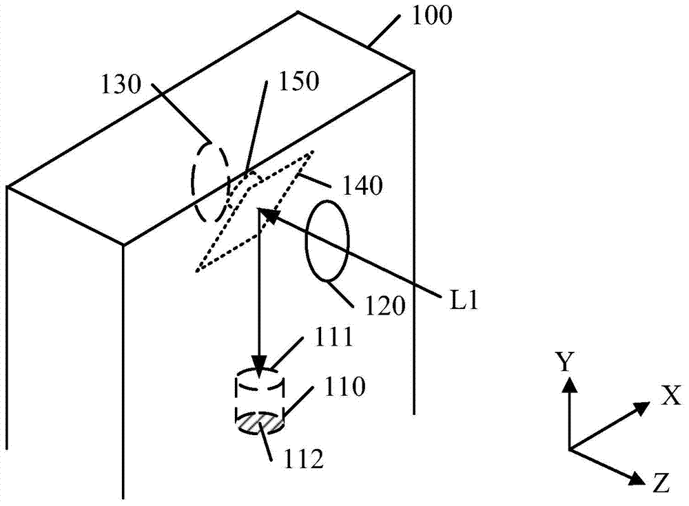
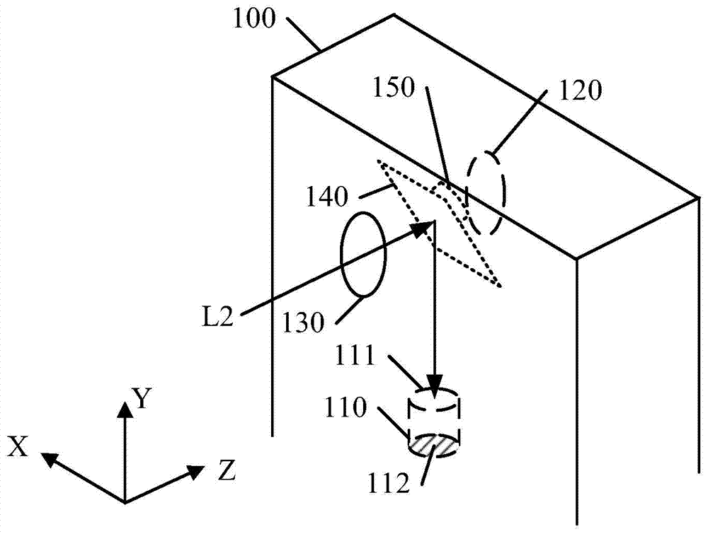
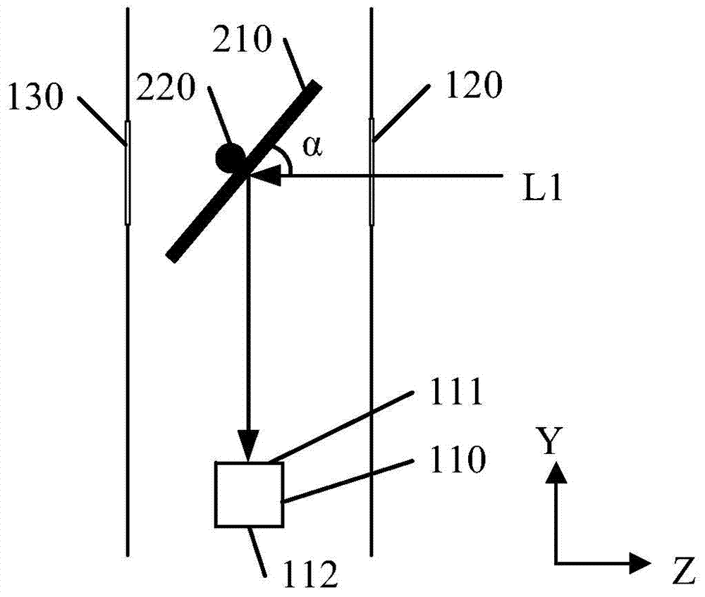
[0016] In order for those skilled in the art to better understand the technical solution of the present invention, the embodiments of the terminal device and the photographing method of the present invention will be described in detail below in conjunction with the accompanying drawings. For the convenience of description, in the following embodiment, a mobile phone capable of taking pictures in at least the front and rear directions is taken as an example, and the same components are given the same reference numerals. However, those skilled in the art should know that the terminal device in the present invention may also be a notebook computer, a tablet computer, or any other electronic device in addition to a mobile phone. In the following drawings, the positive direction of the X-axis is taken as the right side of the terminal device (width direction), the Y-axis is taken as the front side of the terminal device (length direction), and the Z-axis is taken as the front side o...


PUM


Abstract

The invention provides a terminal device and an image-pickup method. With the terminal device and the image-pickup method adopted, multi-direction image pickup can be realized through a single camera lens. The terminal device includes a camera lens, a first light hole, a second light hole, a first light path modulation component and a control component; the camera lens includes a lens and a photosensitive component; the direction of the optical axis of the camera lens is orthogonal to a first direction and a second direction; the first light hole is arranged at the first surface of the terminal device and is configured to make light from the first direction enter the terminal device; the second light hole is arranged at the second surface of the terminal device and is configured to make light from the second direction enter the terminal device; the first light path modulation component is configured to change the direction of the light from the first light hole or the second light hole; the control component is configured to control the first light path modulation component to make light from the first light hole projected into the camera lens when receiving signals of a first shooting mode selected by a user, and is configured to control the first light path modulation component to make the light from the second light hole projected into the camera lens when receiving signals of a second shooting mode selected by the user.

Description

technical field [0001] The present invention relates to camera technology, in particular to a terminal device capable of shooting in multiple directions with a single camera and a camera method. Background technique [0002] Nowadays, with the multifunctionalization of electronic products, cameras are installed on many laptops, tablets, mobile phones and other electronic devices. In order to realize shooting in multiple directions, multiple cameras are often equipped on the device. For example, there are often two cameras on the front and one on the back of the device. However, such a design takes up more space than a single-camera device, which affects the compactness and thinness of the device. Not only that, but multiple cameras lead to a more complex and costly design. In this regard, in order to save costs, the performance of the sub-camera on the front of the device used to realize the Selfie function is often lower than that of the main camera on the back of the de...

Claims


Application Information

Patent Timeline
IPC IPC(8): H04N5/232G03B17/17
Inventor 谭天水刘永华
Owner LENOVO (BEIJING) CO LTD
Learn More