Panoramic video stitching method based on multi-depth image transformation matrix

A transformation matrix, panoramic video technology, applied in the field of video splicing, can solve the problems of large amount of calculation, produce artifacts, interfere with splicing line adjustment, etc., and achieve the effect of fast running speed and small amount of calculation

Inactive Publication Date: 2015-04-15
易麦博视觉有限公司
View PDF7 Cites 30 Cited by
  • Summary
  • Abstract
  • Description
  • Claims
  • Application Information

AI Technical Summary

Problems solved by technology

However, when the number of foreground objects is relatively large, the processing time will be longer, and at the same time, multiple foreground objects will also interfere with the adjustment of the stitching line.
[Document 4] Using depth information to adaptively correct the image stitching matrix can eliminate artifacts; but when there are multiple large depth transformations in the scene, the adaptive correction process will become complicated
[Document 5] and [Document 6] use multiple image transformation matrices to solve the projection matrix in the real scene, and obtain a different transformation matrix for each pixel; this method can obtain high-quality stitching results, but the calculation Large amount, not suitable for real-time requirements of video splicing
[Document 7] proposed an adaptive method for updating the projection matrix, which is applied to the real-time stitching algorithm; but when the moving object is relatively close to the camera, the stitching process produces artifacts, and the effect is not ideal.

Method used


Image

  • Panoramic video stitching method based on multi-depth image transformation matrix
  • Panoramic video stitching method based on multi-depth image transformation matrix
  • Panoramic video stitching method based on multi-depth image transformation matrix

Examples


Embodiment Construction

[0036] Preferred embodiments of the present invention will be described in detail below in conjunction with the accompanying drawings.

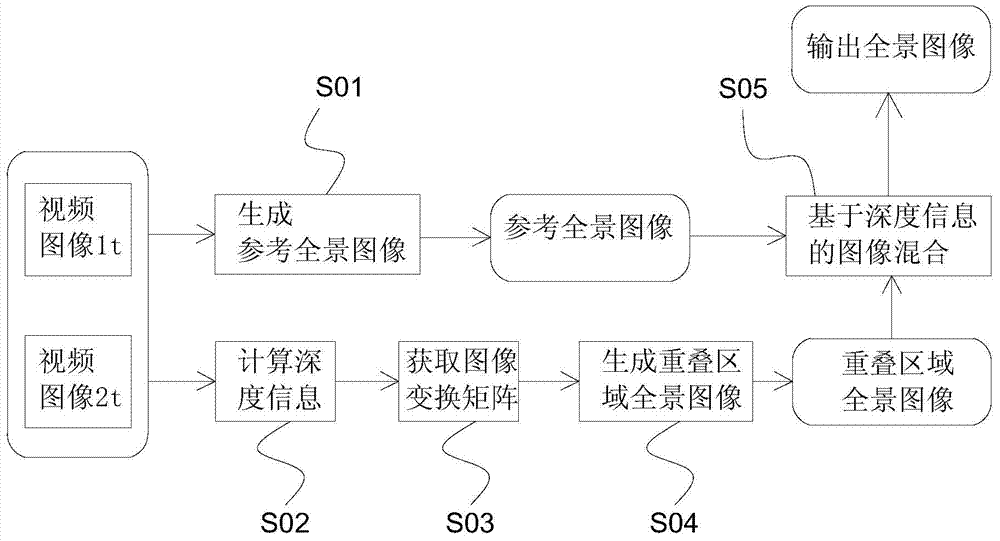
[0037] see Figure 1 to Figure 3 In this embodiment, the panoramic video stitching method based on the multi-depth image transformation matrix of the present invention is described in detail by taking two videos captured by two cameras and including overlapping areas to synthesize a panoramic video as an example.

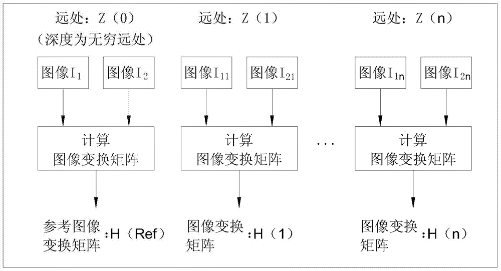
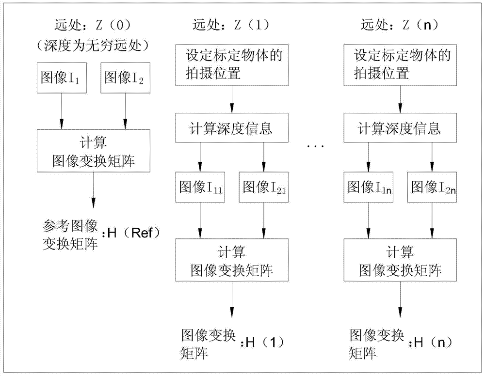
[0038] background calibration process

[0039] Such as figure 1 As shown, the depth level at infinity is marked as Z(0), and the image I with depth at infinity is obtained from a video 1 and get an image with depth at infinity from another video I 2 According to the formula (1), the image transformation matrix H is calculated as the reference image transformation matrix H(Ref); according to the order of depth from far to near, a certain depth information value in the distance is first marked as Z(1), and the two The image I obt...


PUM


Abstract

The invention discloses a panoramic video stitching method based on a multi-depth image transformation matrix. The panoramic video stitching method based on the multi-depth image transformation matrix comprises the following steps: synthesizing a plurality of videos provided with mutually overlapped regions and shot by a plurality of cameras into a panoramic video. The method comprises a background calibration process and a real-time stitching process. A reference planar image transformation matrix with an infinitive depth is obtained in the background calibration process, and besides, other depth information is divided into different depth levels, so that a planar image transformation matrix corresponding to each depth level is obtained; in the real-time stitching process, a reference panoramic image is obtained by using the reference planar image transformation matrix, besides, the current depth information in the overlapped region is calculated, and the panoramic image of the overlapped region is obtained according to the image transformation matrix corresponding to the depth information; finally, the panoramic image of the overlapped region and the reference panoramic image are mixed into the panoramic video image. The method disclosed by the invention can obtain stable, continuous and high-quality panoramic video, and the method has the characteristics of small calculated amount and high running speed.

Description

technical field [0001] The invention relates to a video splicing method, in particular to a panoramic video splicing method based on a multi-depth image transformation matrix. Background technique [0002] Video stitching is an important technique in computer vision. Given multiple videos with overlapping regions, the process of video stitching is to combine these videos on the same viewing plane to form a panoramic video with higher resolution and wider viewing angle. In real life, this technology is applied to various fields such as video surveillance, exhibitions, remote video conferencing, and visual entertainment. [0003] Many application scenarios have put forward the requirements of high-quality composite images and fast real-time operation speed for panoramic videos. The existing video splicing methods have proposed various solutions for this. In actual scenes, foreground objects often produce artifacts near the stitching line. In order to solve this problem, [Do...

Claims


Application Information

Patent Timeline
Patent Type & Authority Applications(China)
IPC IPC(8): H04N13/00G06T5/50G06T7/00
Inventor 余俊池陆骏张凤清高建峰
Owner 易麦博视觉有限公司
Why Eureka
Try Eureka