Spray nozzle device, in particular for spraying a cast strand

A technology for spraying nozzles and casting billets, which is applied to spraying devices, liquid spraying devices, etc., can solve problems such as mutual influence, and achieve the effect of easy matching and simplified processing.

Active Publication Date: 2015-04-15
SMS CONCAST
View PDF9 Cites 5 Cited by
  • Summary
  • Abstract
  • Description
  • Claims
  • Application Information

AI Technical Summary

Problems solved by technology

Problems due to the interaction of air pressure and water pressure or air flow and water flow are not perfectly resolved

Method used


Image

  • Spray nozzle device, in particular for spraying a cast strand
  • Spray nozzle device, in particular for spraying a cast strand
  • Spray nozzle device, in particular for spraying a cast strand

Examples


Embodiment Construction

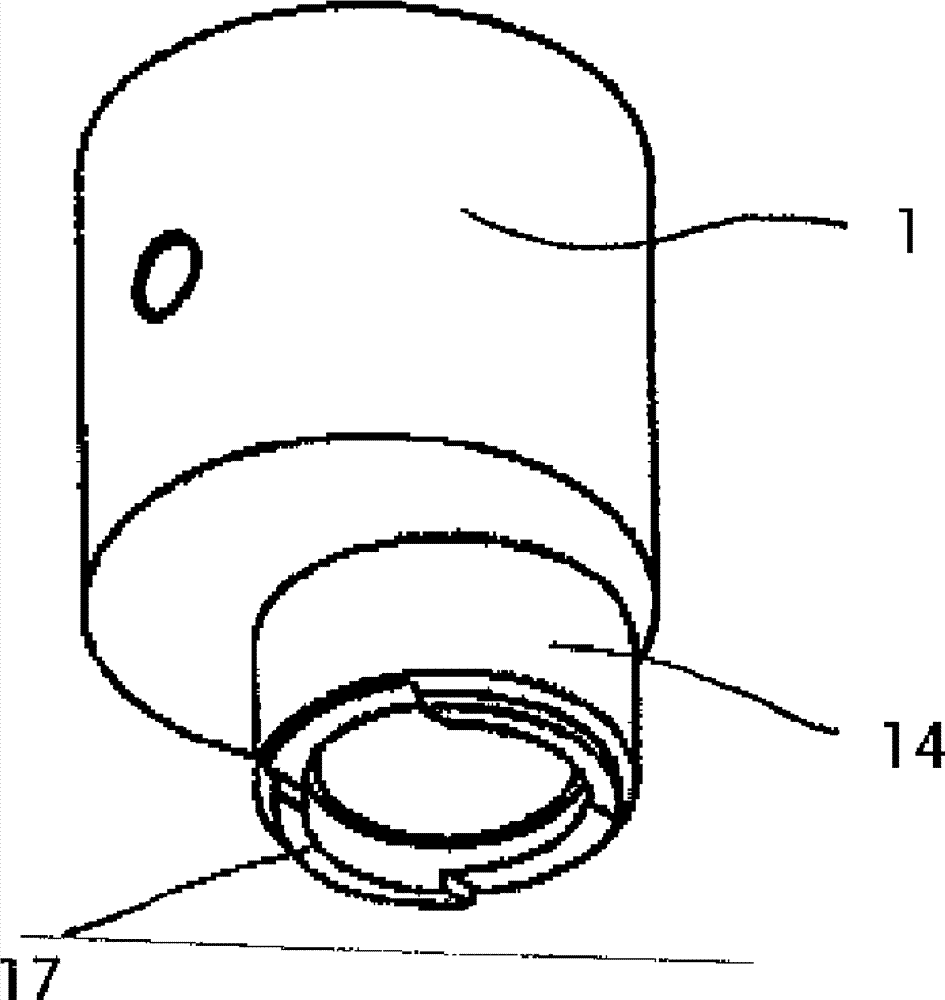
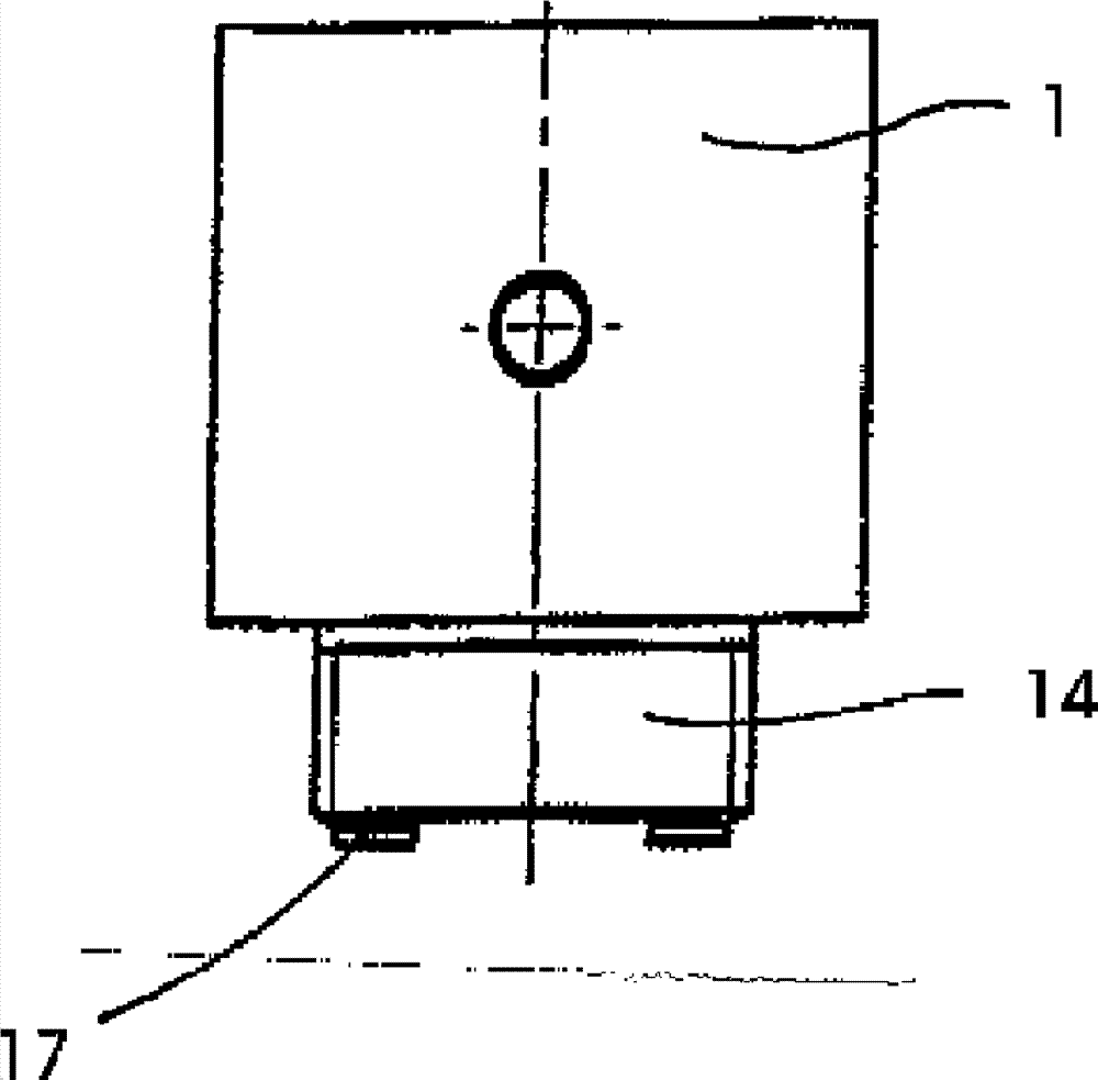
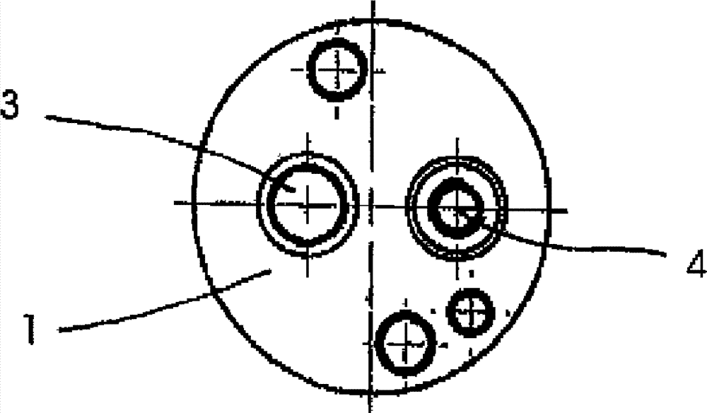
[0020] according to Figure 1 to Figure 4 The spray nozzle unit is used to spray the strand with an air / water mixture in order to cool the strand during casting. The mixing body 1 has a mixing chamber 2 which is provided with an air inlet 3 , a water inlet 4 and a nozzle outlet 5 .

[0021] The mixing chamber 2 of the mixing body 1 is designed in a cylindrical shape. The length of the mixing chamber is approximately twice its internal diameter. The air inlet 3 is arranged in an air inlet nozzle 6 whose top 7 protrudes into the upper region of the mixing chamber. The air inlet nozzle 6 is aligned coaxially to the mixing chamber 2 , and the outer diameter of the air inlet nozzle 6 is here smaller than half the inner diameter of the mixing chamber. In this region, the air inlet nozzle 6 is provided with air outlet bores 9 exiting from the air inlet nozzle in a radial direction approximately transverse to the longitudinal axis of the mixing chamber, which are distributed unifor...


PUM


Abstract

Spray nozzle device comprises a mixing chamber (2) which acts as a diffuser and has a mixing body (1). The mixing chamber is provided with an air inlet (3), a water inlet (4), and a nozzle outlet (5) oriented approximately in alignment with the air inlet through which an air or water mixture exits. The air inlet comprises a region projecting in the mixing chamber, and at least one air outlet hole, which is perpendicular to the longitudinal axis of the mixing chamber. The water enters near the tip through at least one water outlet hole, which is oriented perpendicular to the longitudinal axis.

Description

technical field [0001] The invention relates to a spray nozzle arrangement, in particular for spraying cast strands (Giessstrang), with a mixing body having a diffusively acting mixing chamber, which is provided with an air inlet, a water inlet and is arranged opposite the air inlet. The nozzle outlet on the side of the housing through which the air / water mixture exits. Background technique [0002] Spray nozzles of this type are known for cooling the strand during casting. Here, the aim is to achieve as uniform a cooling effect as possible in order to prevent cracks that can develop in the hot strand during the cooling process. Efforts are therefore made to design the spray nozzle in such a way that the delivered cooling jet is structurally homogeneous. However, the correspondingly required cooling effect differs from case to case, not only due to technological reasons, but also due to the size and / or geometry of the structure to be cast. The conditions of use of the spr...

Claims


Application Information

Patent Timeline
Patent Type & Authority Applications(China)
IPC IPC(8): B05B7/04B22D11/124B05B15/65
CPCB22D11/124B05B7/0483B05B15/065B05B15/65B22D11/1246B22D30/00
Inventor L. 库斯特K. 冯伊纳坦
Owner SMS CONCAST
Why Eureka
Try Eureka