
Multilayer flip-flow screen type screening equipment

A technology of screening equipment and relaxation screen, which is applied in the direction of filter screen, solid separation, grille, etc., can solve the problems of blocked screen holes, the main frame of the screen machine does not vibrate, and the limitations of the comprehensive application of the screen machine. Effect of limited width and improved processing performance

Inactive Publication Date: 2015-04-22
AURY TIANJIN IND TECH
View PDF0 Cites 4 Cited by
  • Summary
  • Abstract
  • Description
  • Claims
  • Application Information

AI Technical Summary

Problems solved by technology

[0002] The existing relaxation screen structure is a crank connecting rod structure. The rotation of the crankshaft drives the movement of the movable frame, which is generated by the relative movement of the main frame and drives the relaxation of the flexible sieve plate. However, the main frame of the screen machine with this structure does not vibrate. Comprehensive application has limitations. For example, if a double-layer structure screen is used, the upper screen surface is a traditional fixed screen surface, and the screening operation cannot be performed because the screen surface has no movement.
Moreover, sticky and wet materials are prone to problems such as blocked screen holes and sticky screen surface during the screening process, which make the screening efficiency low. It is necessary to further improve the existing relaxation screen.

Method used


Image

  • Multilayer flip-flow screen type screening equipment
  • Multilayer flip-flow screen type screening equipment
  • Multilayer flip-flow screen type screening equipment

Examples

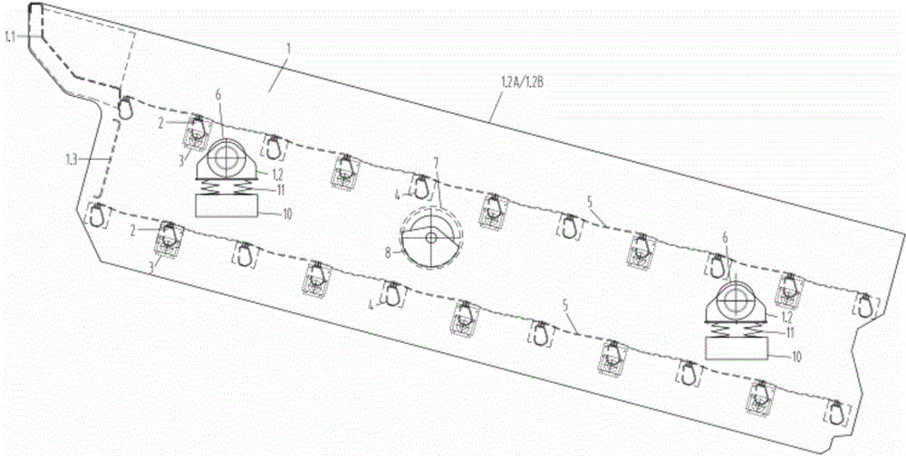
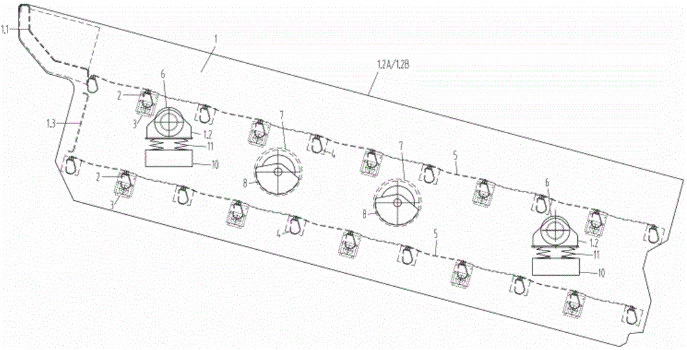
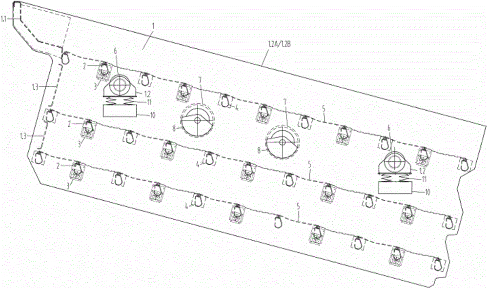

Embodiment Construction

[0025] A specific embodiment of the present invention will be described below in conjunction with the accompanying drawings.

[0026] Such as Figure 1-4 As shown, the present invention provides a kind of multi-layer relaxation sieve type screening equipment, comprising a main vibrating body 1, the main vibrating body 1 is composed of a fixed beam 4, a supporting beam 6, an intermediate shaft protective sleeve beam 7, a feeding box 1.1, The left side plate 1.2A and the right side plate 1.2B are connected to form a frame structure, which is characterized in that it also includes a plurality of additional vibrating bodies, the additional vibrating bodies are fixed on the main vibrating body 1 through the swing seat 3, each The additional vibrating body is composed of a floating beam 2 and a swing seat 3 connected to the two ends of the floating beam 2. Each floating beam 2 is connected to the main vibrating body 1 through a swing seat 3. The fixed beam 4 and the floating beam 2 ...


PUM


Abstract

The invention belongs to the technical field of screening and particularly relates to multilayer flip-flow screen type screening equipment. Additional vibrating bodies are fixed to a main vibrating body through swinging bases. Each additional vibrating body is composed of a floating cross beam and the swinging bases connected with the two ends of the floating cross beam. Each floating cross beam is connected to the main vibrating body through the corresponding swinging bases. Fixed cross beams and the floating cross beams are arranged alternately. Each fixed cross beam and the adjacent floating cross beam are connected with each other through a detachable polyurethane sieve plate. Independent vibrating sources are mounted on a left side plate and a right side plate of the main vibrating body respectively. The vibrating source mounted on the left side plate and the vibrating source mounted on the right side plate are connected through an intermediate shaft. An intermediate shaft protective sleeve beam connected with the left side plate and the right side plate is mounted outside the intermediate shaft. The multilayer flip-flow screen type screening equipment has the advantages that multiple vibrating systems are additionally arranged on the main vibrating body according to the double-mass subresonance principle, the screening machine with one power source supplying power to two kinds of motion is realized, and the screening efficiency is high.

Description

technical field [0001] The invention belongs to the technical field of screening, in particular to a multi-layer relaxation screen type screening equipment. Background technique [0002] The existing relaxation screen structure is a crank connecting rod structure. The rotation of the crankshaft drives the movement of the movable frame, which is generated by the relative movement of the main frame and drives the relaxation of the flexible sieve plate. However, the main frame of the screen machine with this structure does not vibrate. Comprehensive application has limitations. For example, if a double-layer screen machine is used, the upper screen surface is a traditional fixed screen surface, and the screening operation cannot be performed because the screen surface has no movement. Moreover, sticky and wet materials are prone to problems such as blocked screen holes and sticky screen surface during the screening process, which make the screening efficiency low, and further i...

Claims


Application Information

Patent Timeline
Patent Type & Authority Applications(China)
IPC IPC(8): B07B1/28B07B1/46
CPCB07B1/28B07B1/46
Inventor 张晋喜刘波
Owner AURY TIANJIN IND TECH
Learn More