Electric welding fixture capable of being controlled by one hand and provided with welding shielding lens and use method of electric welding fixture

A lens and handle technology, which is applied to the characteristics of welding rods, electrode support devices, and support devices for protection, etc., can solve problems such as inconvenience, and achieve the effect of simple use method, lightening labor intensity, and preventing direct exposure.

Active Publication Date: 2015-04-22
桐城市建设投资发展有限责任公司
View PDF5 Cites 6 Cited by
  • Summary
  • Abstract
  • Description
  • Claims
  • Application Information

AI Technical Summary

Problems solved by technology

[0002] When welding objects, welding operators usually hold the welding clip in one hand and the face mask in the other. When it is necessary to control the welding object, it is often very inconvenient to hold the face mask with one hand

Method used


Image

  • Electric welding fixture capable of being controlled by one hand and provided with welding shielding lens and use method of electric welding fixture
  • Electric welding fixture capable of being controlled by one hand and provided with welding shielding lens and use method of electric welding fixture
  • Electric welding fixture capable of being controlled by one hand and provided with welding shielding lens and use method of electric welding fixture

Examples


Embodiment Construction

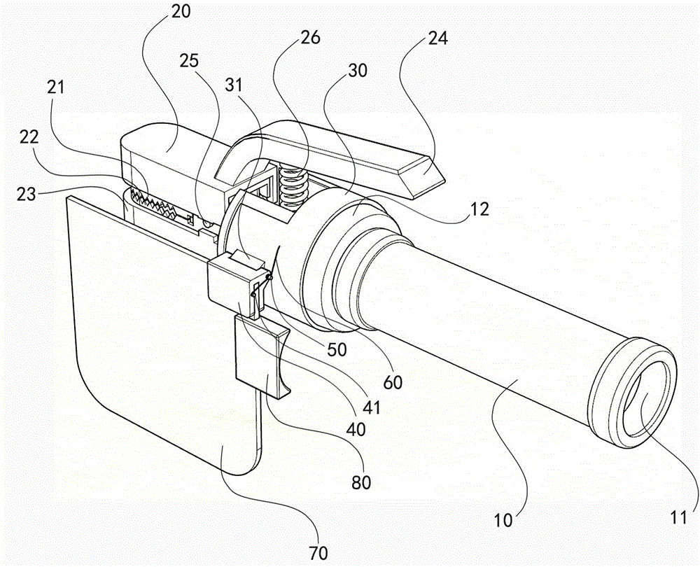
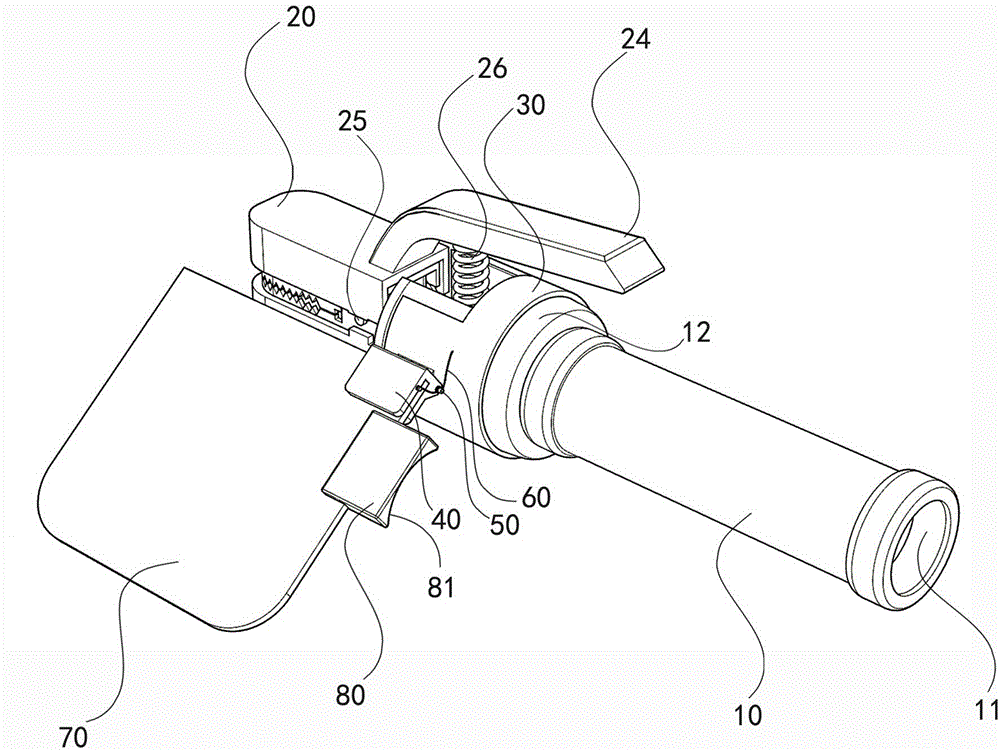
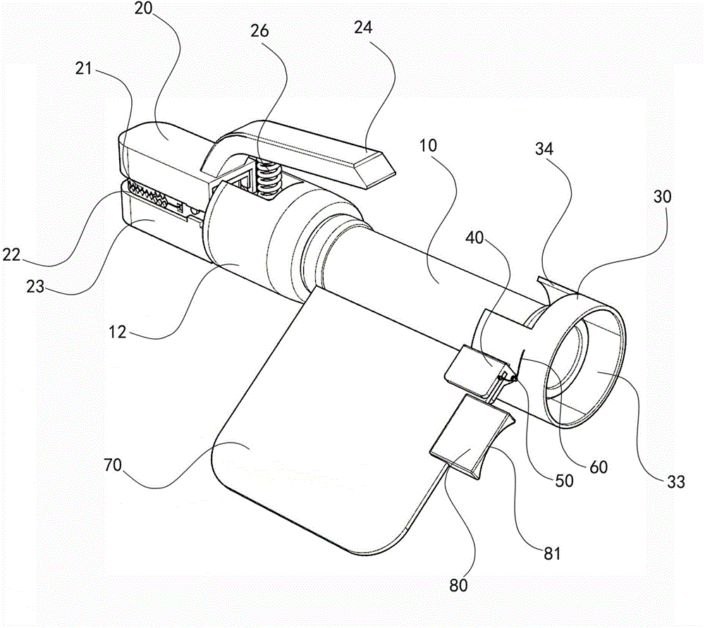
[0019] Below, the present invention will be further described in conjunction with the accompanying drawings and embodiments.

[0020] figure 1 — Figure 5 It is an embodiment of the present invention. As shown in the figure, a single-handed electric welding clamp with welding shading lens includes a handle 10, a wire guide hole 11, a front end of the handle 12, an upper insulating sleeve 20, and an upper copper tooth 21. , lower copper tooth 22, lower insulating sleeve 23, handle 24, large shaft pin 25, large spring 26; and ferrule 30 set on the handle front end 12; 33. Positioning block 40, spring clip 41, positioning block hole 42, positioning clip groove 43, limiting block 44, small shaft pin 50, small spring 60, positioning elbow 61, spring ring 62, tapered head 63, black Welding lens 70, side block 80, concave arc edge 81, side block clip groove 82; handle 10, wire guide hole 11, handle front end 12 and lower copper tooth 22 form a whole, and upper copper tooth 21 and h...


PUM


Abstract

An electric welding fixture capable of being controlled by one hand and provided with a welding shielding lens comprises a handle, a wire guide hole, a handle front end, an upper insulating sleeve, an upper copper tooth, a lower copper tooth, a lower insulating sleeve, a hand grip, a large shaft pin, a large spring, a sleeve ring, a protruding head, an inner sleeve ring, a positioning block, a spring clamping strip, a positioning block hole, a positioning clamping groove, a limiting block, a small shaft pin, a small spring, a positioning elbow, a spring ring, a conical head, the black electric welding lens, an edge block, a concave arc edge and an edge block clamping groove, wherein the front end of the handle is sleeved with the sleeve ring, and the sleeve ring is provided with the protruding head, the inner sleeve ring, the positioning block, the spring clamping strip, the positioning block hole, the positioning clamping groove, the limiting block, the small shaft pin, the small spring, the positioning elbow, the spring ring, the conical head, the black electric welding lens, the edge block, the concave arc edge and the edge block clamping groove. An elastic rubber ring is fixed into the sleeve ring. The elastic rubber ring is in interference fit with the front end of the handle. The small shaft pin makes the protruding head on the sleeve ring connected with the positioning block through a pin by means of a protruding head hole and a positioning block hole. By means of the welding fixture, a user can complete the welding work and control the electric welding lens additionally arranged at the front end of the handle by one hand in the welding work process, an operator can emancipate a hand which holds a mask, and the welding efficiency and welding quality can be easily improved.

Description

technical field [0001] The invention relates to an electric welding tool, in particular to an electric welding clamp with a welding shading lens which can be manipulated by one hand. Background technique [0002] When welding objects, electric welding operators usually hold the welding clip in one hand and the face mask in the other hand. When it is necessary to control the welding object, it is often very inconvenient to hold the face mask with one hand. Contents of the invention [0003] Aiming at the deficiencies in the prior art, the invention provides a single-handed electric welding clip with a welding shading lens and a use method thereof. [0004] The object of the present invention is achieved in this way: a single-handed electric welding clip with welding shading lens is characterized in that the single-handed electric welding clip with welding shading lens mainly includes a handle, a wire guide hole, a handle Front end, upper insulating sleeve, upper copper too...

Claims


Application Information

Patent Timeline
Patent Type & Authority Applications(China)
IPC IPC(8): B23K9/29
CPCB23K9/29
Inventor 王永健王东颖
Owner 桐城市建设投资发展有限责任公司
Why Eureka
Try Eureka