
Workpiece holder in ion beam polishing device

A workpiece fixture and ion beam technology, applied in the field of workpiece fixtures, can solve the problems of inconvenience, time-consuming, low processing efficiency, etc., and achieve the effect of eliminating complicated operations

Inactive Publication Date: 2015-04-22
INST OF OPTICS & ELECTRONICS - CHINESE ACAD OF SCI
View PDF7 Cites 12 Cited by
  • Summary
  • Abstract
  • Description
  • Claims
  • Application Information

AI Technical Summary

Problems solved by technology

[0003] The patent application number 201110329856.X discloses a workpiece clamping device in the process of ion beam polishing. Although the specific structure and clamping method are introduced in detail, and the precise clamping of the workpiece can be realized, the described method uses a dial gauge The way of playing the meter is very inconvenient in the actual operation process. It needs a series of steps such as meter installation, meter adjustment, and back and forth adjustment. It takes a lot of time to clamp a workpiece, and the processing efficiency is not high.

Method used


Image

  • Workpiece holder in ion beam polishing device
  • Workpiece holder in ion beam polishing device
  • Workpiece holder in ion beam polishing device

Examples


Embodiment Construction

[0045] In order to make the object, technical solution and advantages of the present invention clearer, the present invention will be described in further detail below in conjunction with specific embodiments and with reference to the accompanying drawings.

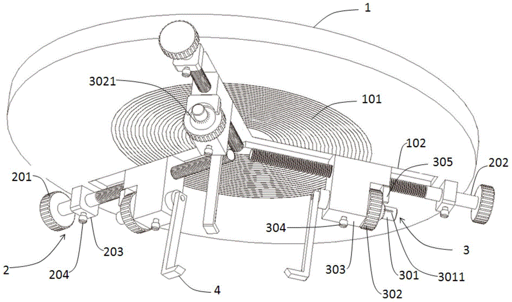
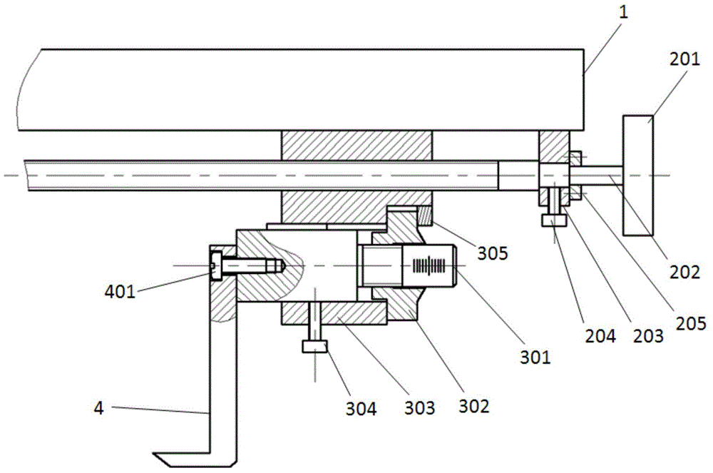
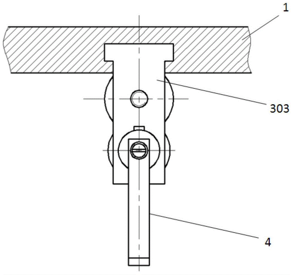
[0046] figure 1 Shown is a three-dimensional schematic view of one embodiment of the invention. On the lower surface of the circular reference plate 1 there are several concentric circle coarse-adjustment scale lines 101 concentric with it, and the scale lines are equally spaced, with a distance of 3 millimeters. The three T-shaped slots 102 are evenly distributed in the radial direction. In addition, there are three sets of coarse adjustment assemblies 2, three sets of fine adjustment assemblies 3 and three clamping jaws 4, and each set of coarse adjustment assemblies 2 and coarse adjustment assemblies 3 is used to adjust a clamping jaw 4 to move along the direction of the T-shaped slot. Combine below Figure 2 to Fig...


PUM


Abstract

The invention discloses a workpiece holder in an ion beam polishing device. The workpiece holder comprises a circular reference disc, clamping jaws, a rough adjustment mechanism and a fine adjustment mechanism. Multiple concentric circle marks with the reference disc as the concentric center are arranged on the lower surface of the circular reference disc, wherein the marks serve as rough adjustment references. The clamping jaws can be driven by the rough adjustment mechanism and the fine adjustment mechanism to radially move on the reference disc. When a workpiece is clamped, it is guaranteed that the center of the workpiece is aligned with the center of a clamping disc, so that the workpiece is accurately located and clamped. The workpiece holder has the advantages of being convenient and quick to operate, the workpiece can be rapidly clamped, and device machining efficiency can be improved to a great extent.

Description

technical field [0001] The invention belongs to the field of precision optical parts processing, and in particular relates to a workpiece fixture in ion beam polishing equipment. Background technique [0002] As a non-contact deterministic removal processing method, ion beam polishing has the advantages of high processing precision and no residual stress, and is now more and more used in the processing of high-precision optical components. During the ion beam polishing process, the high-energy ions generated by the ion source bombard the surface of the optical element to remove materials, and the bombardment position and time correspond to each other. The calculation of the processing dwell time needs to be based on accurate position coordinates. Therefore, the precise positioning of the workpiece in the ion beam polishing equipment is closely related to the processing accuracy. In the ion beam polishing equipment, the positioning of the workpiece is based on the center of ...

Claims


Application Information

Patent Timeline
Patent Type & Authority Applications(China)
IPC IPC(8): B24B13/005
CPCB24B13/005
Inventor 付韬韬李云王安定
Owner INST OF OPTICS & ELECTRONICS - CHINESE ACAD OF SCI
Learn More