Supercharge Your Innovation With Domain-Expert AI Agents!

A pull rod balancing device of a two-plate type injection molding machine

A balancing device and injection molding machine technology, applied in the field of injection molding, can solve the problems of increasing the axial size of the injection molding machine, increasing the production cost, etc., and achieve the effects of convenient control, prolonging the life of the oil cylinder, and reducing the wear and vibration of the tie rod.

Active Publication Date: 2015-04-22
TEDERIC MACHINERY
View PDF7 Cites 0 Cited by
  • Summary
  • Abstract
  • Description
  • Claims
  • Application Information

AI Technical Summary

Problems solved by technology

Although this invention solves a series of problems caused by the self-weight of the tie rod, the added tie rod support increases the axial dimension of the injection molding machine and also increases the production cost

Method used


Image

  • A pull rod balancing device of a two-plate type injection molding machine
  • A pull rod balancing device of a two-plate type injection molding machine
  • A pull rod balancing device of a two-plate type injection molding machine

Examples


Embodiment 1

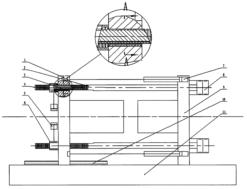
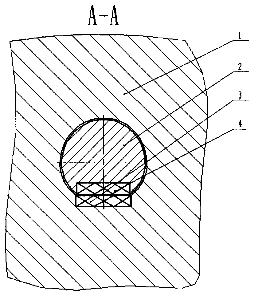
[0015] The present invention is a two-platen injection molding machine pull rod balance device, figure 1 As shown, the main part is composed of movable template 1, electromagnet one 3, electromagnet two 4, pull rod 2 and frame 11; One end of the tie rod 2 is connected to the piston rod of the clamping cylinder 8, the clamping cylinder 8 is fixed on the fixed platen 9, and the other end of the tie rod 2 is processed into a trapezoidal tooth groove and passes through the tie rod groove of the movable platen 1. Pull bar 2 has that section of trapezoidal tooth groove to mill out a plane axially, process a square groove in this plane, put into electromagnet 2 4 in the groove. The length of the square groove is determined by the mold opening distance of the movable template 1, as long as the square groove on the tie rod 2 is greater than the mold opening distance. The closing oil cylinder 5 is fixed on the movable template 1, and the piston rod of the closing oil cylinder 5 is conn...

Embodiment 2

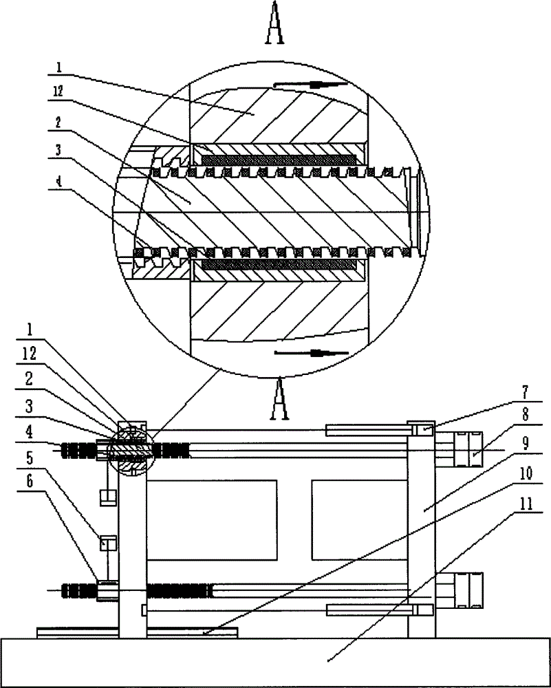
[0020] On the basis of Embodiment 1, an electromagnet sleeve 12 is fixed in the pull rod mounting hole of the movable template 1, and the electromagnet 3 is embedded in the electromagnet sleeve 12 along the circumferential direction, as image 3 , 4 As shown, four or more electromagnets 3 can be embedded in the circumferential direction of the electromagnet sleeve 12, and the electromagnet 4 is fixed at the corresponding position of the pull rod 2 and the electromagnet 3, that is, the trapezoidal convex teeth of the pull rod 2 are processed along the circumferential direction. Groove, electromagnet 2 4 is embedded in the groove of the trapezoidal convex teeth of pull rod 2, electromagnet 1 3 and electromagnet 2 4 have the same circumferential number and are installed in one-to-one correspondence, because the closer the distance between the two electromagnets, the greater the electromagnetic force, Therefore, the circumferential electromagnetic force not only overcomes gravity ...


PUM


Abstract

A pull rod balancing device of a two-plate type injection molding machine is disclosed. A main body part comprises a moving mould board, first electromagnets, second electromagnets, pull rods and a rack. One end of each pull rod is connected to a piston rod of a mould clamping oil cylinder, and the other end of the corresponding pull rod is provided with a trapezoid alveoli and penetrates one of pull rod grooves of the moving mould board. The mould clamping oil cylinder is fixed to a fixed mould board. Planes are milled along the axial direction at trapezoid alveoli ends of the pull rods, square grooves are machined in the planes, and the second electromagnets are put into the square grooves. The moving mould board is fixed to closing oil cylinders and can slide along a dovetailed way along with the pull rods. The pull rods can slide freely along the pull rod grooves of the moving mould board when trapezoid teeth on flashboards and trapezoid teeth of the pull rods are separated. Square grooves are machined in the pull rod grooves of the moving mould board, and the first electromagnets are put into the square grooves. The pull rod balancing device balances self weights of the pull rods by utilization of force generated by the electromagnets respectively disposed in the pull rods and the moving mould board, achieves objectives of reducing vibration and prolonging service lifetime of the oil cylinders, and is rapid in electromagnet action. Input electric current can achieve programmable control of the electromagnetic force.

Description

technical field [0001] The invention relates to the field of injection molding, in particular to a tie rod balancing device for an injection molding machine in the field of two-platen injection molding Background technique [0002] Existing two-platen injection molding machines are mainly divided into two types: compound type and direct pressure type. The compound type two-platen machine needs to undergo mechanical conversion, that is, a secondary action to lock the mold, and is also called mechanical hydraulic type two-platen type. The pull rods of the compound two-platen machine slide relatively in the pull rod grooves of the movable template, and the mold is quickly opened and closed by the small mold moving cylinder. After the mold is closed, the opening and closing gates on the movable template are closed, and the movable template and the pull rod Fix them together, and then lock the mold by the big clamping cylinder. This structure solves the problem that the force an...

Claims


Application Information

Patent Timeline
Patent Type & Authority Applications(China)
IPC IPC(8): B29C45/64
CPCB29C45/68B29C2045/645
Inventor 周宏伟李立峰李斌斌林武
Owner TEDERIC MACHINERY
Features
  • R&D
  • Intellectual Property
  • Life Sciences
  • Materials
  • Tech Scout
  • Unparalleled Data Quality
  • Higher Quality Content
  • 60% Fewer Hallucinations
Learn More