
Hydraulic power cart

A technology for hydraulic power and power vehicles, which is applied to power units, wheels, vehicle components, etc., and can solve problems such as limited application scope, air leakage, tire blowout, and long charging time.

Pending Publication Date: 2015-04-22
象山众用洁能设备厂
View PDF6 Cites 0 Cited by
  • Summary
  • Abstract
  • Description
  • Claims
  • Application Information

AI Technical Summary

Problems solved by technology

[0003] However, due to the limited battery capacity of electric vehicles, the mileage is short, the charging battery needs to be parked and special charging equipment is used, and the charging time is longer. In many respects, it is still inferior to internal combustion engine vehicles, and the scope of application is limited.
[0004] The current internal combustion engine vehicles and battery vehicles use pneumatic tires. Pneumatic tires are prone to defects such as air leakage and tire blowout, which have caused great losses to life and property.

Method used


Image

  • Hydraulic power cart
  • Hydraulic power cart
  • Hydraulic power cart

Examples


Embodiment Construction

[0019] The present invention will be further described below in conjunction with the accompanying drawings and specific embodiments, but the present invention is not limited to these embodiments.

[0020] The present invention covers any alternatives, modifications, equivalent methods and schemes made on the spirit and scope of the present invention. In order to provide the public with a thorough understanding of the present invention, specific details are set forth in the following preferred embodiments of the present invention, but those skilled in the art can fully understand the present invention without the description of these details. In addition, for the sake of illustration, the drawings of the present invention are not completely drawn according to the actual scale, and are described here.

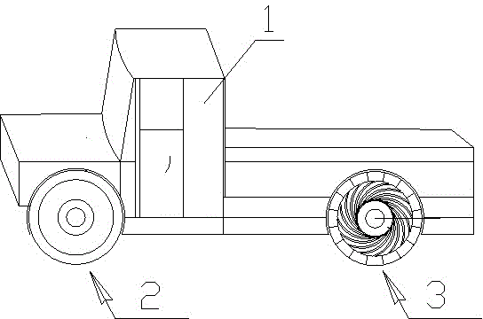
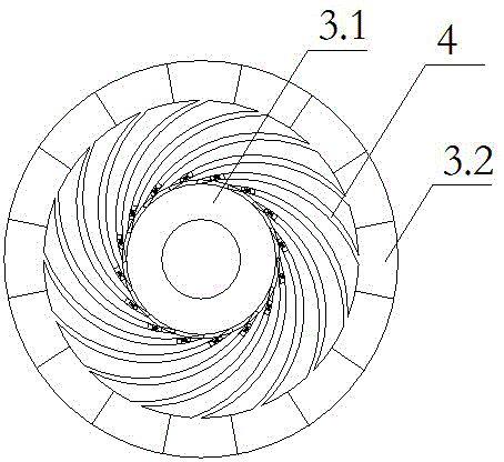
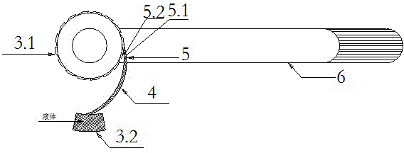
[0021] Such as figure 1 , 2 , 3 and 4, the hydraulic power car of the present invention includes a car body 1, a driving wheel 2 and a driven wheel 3, and the driving wheel 2 a...


PUM


Abstract

The invention discloses a hydraulic power cart. The hydraulic power cart comprises a cart body (1), driving wheels (2) and driven wheels (3), wherein the driving wheels (2) and the driven wheels (3) are installed on the lower portion of the cart body (1); each driven wheel (3) comprises a hub (3.1) and a hydraulic tire; each hydraulic tire is composed of multiple hydraulic cavities (3.2) which are evenly installed on the outer periphery of the corresponding hub (3.1); each hydraulic cavity (3.2) is connected with a corresponding hydraulic pipeline (4); the hydraulic pipelines (4) are connected with hydraulic piston mechanisms (5) which are connected with a hydraulic power transmission mechanism; the hydraulic power transmission mechanism is connected with an electric generator to enable the electric generator to generate electricity. By the adoption of the hydraulic power cart, hydraulic pressure can be utilized for charging a storage battery, the endurance range is prolonged, and therefore the application range is enlarged.

Description

technical field [0001] The invention relates to the field of power vehicles, in particular to a hydraulic power vehicle. Background technique [0002] Fuel-fueled internal-combustion engine vehicles have become the main means of transportation for people on land. They are divided into gasoline vehicles and diesel vehicles. There are three driving modes: front drive, rear drive, and front and rear drive. Most of the vehicles are rear drive. As we all know, internal combustion engine vehicles not only consume precious non-renewable petroleum resources, but also seriously pollute the environment. For this reason, people are looking for new energy sources to replace fuel oil. Although many new energy sources have been developed, they are mainly based on electric energy. That is to promote and use electric vehicles to replace internal combustion engine vehicles, and support them in government policies to achieve energy saving and environmental protection. [0003] However, due ...

Claims


Application Information

Patent Timeline
IPC IPC(8): B60K8/00B60B9/20
Inventor 周大川
Owner 象山众用洁能设备厂
Learn More