Span change structure of beam lifter

A beam lifting machine and main beam technology, which is applied in the direction of traveling mechanism, crane, trolley crane, etc., can solve the problems of long time and high labor intensity when changing the span, so as to reduce labor intensity, make it convenient to change the span, and improve the operation efficiency of the span change. Effect

Inactive Publication Date: 2015-04-22
SINOHYDRO BUREAU 7 CO LTD
View PDF7 Cites 0 Cited by
  • Summary
  • Abstract
  • Description
  • Claims
  • Application Information

AI Technical Summary

Problems solved by technology

The invention solves the problems of long span-changing time and high labor intensity, and meets the requirements for convenient span-changing hoisting operation of the beam lifting machine

Method used


Image

  • Span change structure of beam lifter
  • Span change structure of beam lifter
  • Span change structure of beam lifter

Examples


Embodiment Construction

[0023] The present invention is further described below in conjunction with embodiment. The examples are used to illustrate the present invention, and do not limit the scope of protection of the present invention in any way.

[0024] combine Figure 1 to Figure 5 .

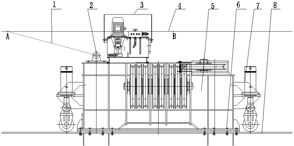
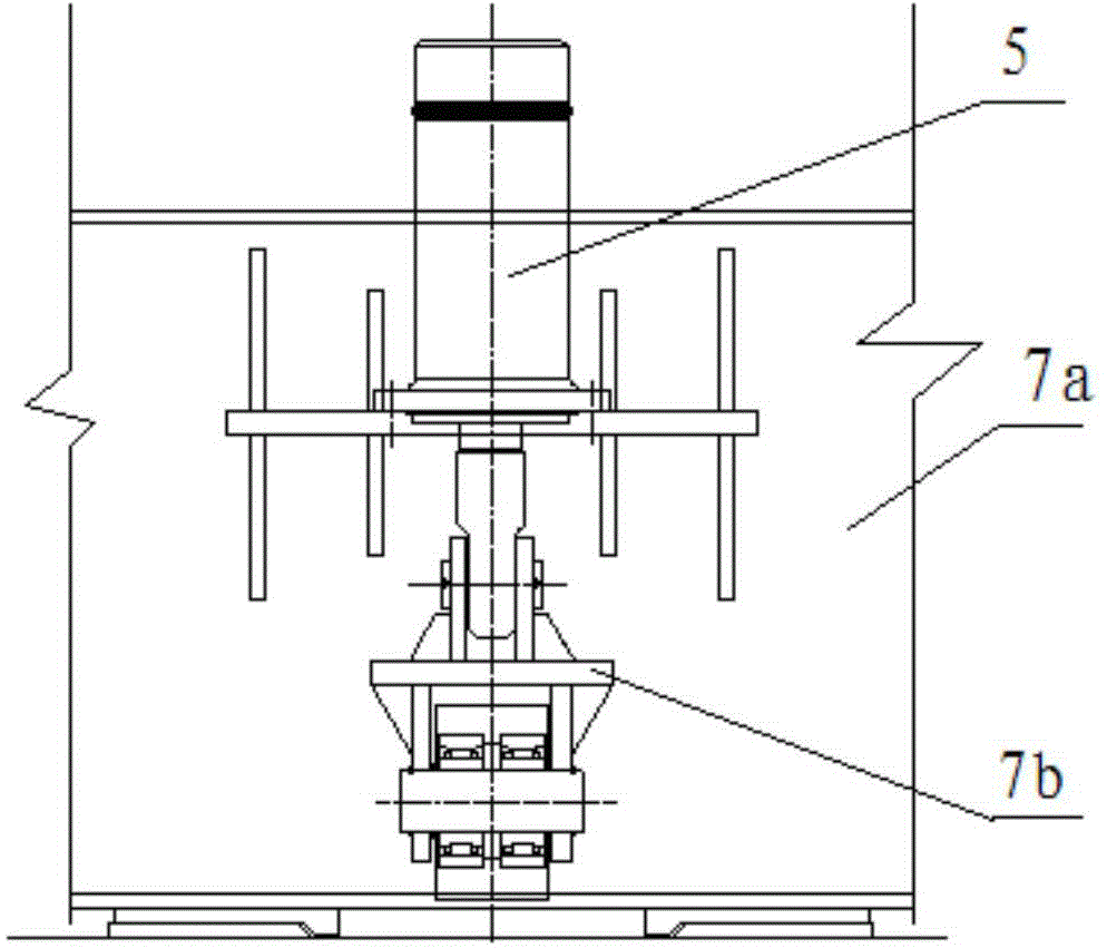
[0025] As shown in the figure, the beam lifting machine has a variable-span structure. The beam lifting machine is a kind of gantry crane, including the main beam 8, the variable-span crown crane 5 and the connecting bolts 6 between the main beam 8 and the variable-span crown crane 5, and the front and rear of the variable-span crown crane 5. Both ends are provided with running assembly 7, which includes moving roller 7b and vertical jacking cylinder 7a; variable-span crane 5 has lifting lug 2 and is detachably connected with hoist through wire rope 1.

[0026] The running assembly 7 is provided with at least 4 groups at the front and rear ends of the variable-span crane 5 .

[0027] The running assembly 7 is c...


PUM


Abstract

The invention discloses a span change structure of a beam lifter. The beam lifter is a portal crane and comprises a main beam, a span change crown block and a connection bolt for the main beam and the span change crown block, wherein walking assemblies are arranged at the front and rear ends of the span change crown block; each walking assembly comprises a mobile idler wheel and a vertical jacking oil cylinder; the span change crown block is provided with a lifting lug to be detachably connected with a winch through a steel wire rope; at least four groups of walking assemblies are arranged at the front and rear ends of the span change crown block, and are fixedly connected with the span change crown block through connection plates; the jacking oil cylinders are fixed above the connection plates; the movable idler wheels are arranged below the connection plate and connected with the jacking oil cylinders through support shafts; the beam lifter is further provided with a guiding and positioning device. According to the span change structure of the beam lifter, the site conditions are reasonably utilized so that the span change is convenient; the original hydraulic system is utilized for controlling the vertical jacking oil cylinders at four corners so that the jacking and falling actions of the main beam are realized by controlling the stretching of the oil cylinder; the span change operation is realized through the traction of the steel wire rope of the winch. Therefore, the span change operation efficiency is well improved and the labor intensity is alleviated under the condition that the safety is ensured.

Description

technical field [0001] The invention belongs to the technical field of hoisting machinery and equipment, and in particular relates to a variable-span structure of a beam lifting machine applied in the technical field of railway simply supported box girder hoisting machinery and equipment. Background technique [0002] The beam lifting machine is a heavy-duty gantry crane, which is mainly used for lifting 32m, 28m, 24m, 20m double-line full-hole box-shaped concrete beams for high-speed railways (passenger dedicated lines). The double-line full-hole box-shaped concrete beams with different spans can be lifted, moved, and loaded in the beam yard, and the hoisting operation can only be realized by changing the span of the variable-span crane. [0003] The existing span-changing method of the beam lifting machine is a step-by-step span-changing design, which uses a hydraulic cylinder to move horizontally on the slide to realize the span-changing. A step cycle includes: fixing the...

Claims


Application Information

Patent Timeline
Patent Type & Authority Applications(China)
IPC IPC(8): B66C19/00
CPCB66C19/00B66C9/14B66C9/16
Inventor 马先科谭德明卿朝晖易海军陈良郑鹏鹏李付军
Owner SINOHYDRO BUREAU 7 CO LTD
Why Eureka
Try Eureka