Rail layer walking process automatic span variation device and span variation method

A track-laying machine and automatic technology, applied in the direction of laying track, track, track maintenance, etc., can solve the problem of time-consuming and labor-intensive, and can not achieve zero-time crossing station and span change operation, etc., to improve the construction speed and facilitate the interval change. Operation, the effect of reducing auxiliary cost input

Active Publication Date: 2017-03-01
(SUZHOU) RAIL TRANSIT SCI & TECH RES INST CO LTD SHANGHAI CIVIL ENG GRP OF CREC +2
View PDF6 Cites 6 Cited by
  • Summary
  • Abstract
  • Description
  • Claims
  • Application Information

AI Technical Summary

Problems solved by technology

Using this method to change the span: Although the spanning operation time is accelerated and the safety risk of the spanning is reduced, it is still necessary to stop, jack up, lay a temporary traverse track, and manually or electrically drive the spanning during the interval spanning, which is time-consuming and labor-intensive , it is impossible to achieve zero time-consuming cross-station operation
[0005] In summary, the existing track-laying construction devices and methods need to be shut down to switch between different working surface spans in practical applications, which takes up effective track-laying operation time. Time-consuming has become an inevitable trend. Therefore, it is an inevitable trend to develop a track-laying device and method that does not require any auxiliary equipment, can automatically change the span during the traveling process, realize zero time-consuming operation surface change, reduce a lot of labor, and is energy-saving and environmentally friendly.

Method used


Image

  • Rail layer walking process automatic span variation device and span variation method
  • Rail layer walking process automatic span variation device and span variation method
  • Rail layer walking process automatic span variation device and span variation method

Examples


Embodiment 1

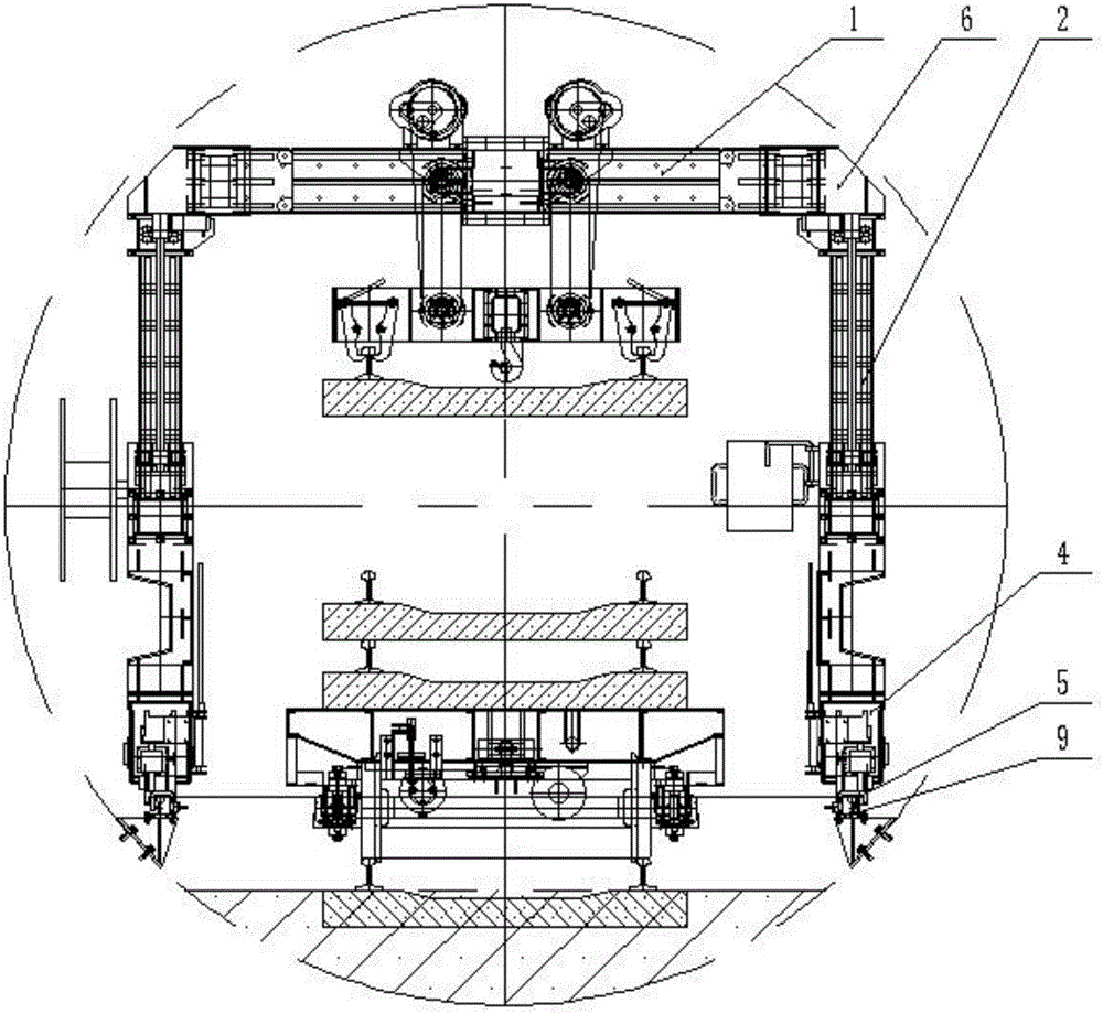
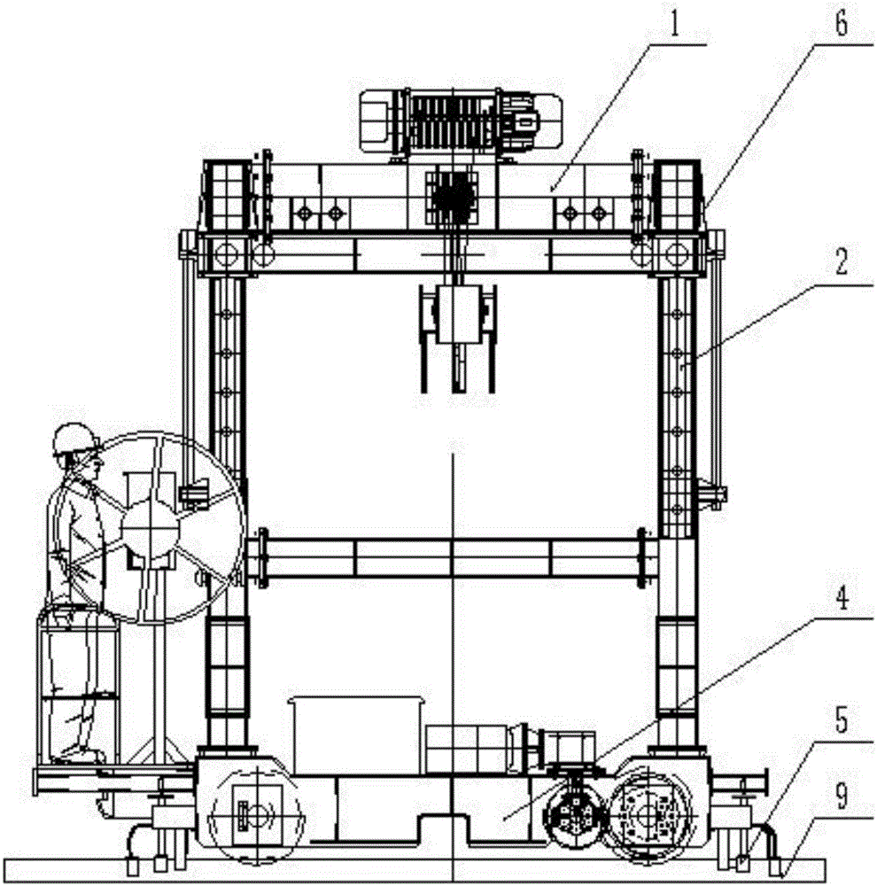
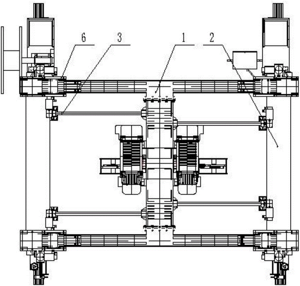
[0040] The automatic span change device during the track laying machine such as figure 1 , figure 2 , image 3 As shown, the main structural design of the present invention: the track-laying machine adopts the guide column type upper beam (1) and the upper beam guide sleeve (6) sliding mechanism, and the top of the leg (2) is fixedly connected with the upper beam guide sleeve (6). The bottom ends of the supporting legs (2) are fixed on the traveling beam (4), and an inductor (5) is respectively arranged on the side of the running track at the lower parts of the front and rear ends of the traveling beam (4). Traversing mechanism (3) drive motor is fixed on the support leg (2) longitudinal beam, and screw mandrel one end is connected with drive motor, and the other end is screwed in the articulated nut on the guide post type upper beam (1).

[0041]In addition, the auxiliary transition rail (7) is designed for the track-laying machine to change the span from the main line run...

Embodiment 2

[0043] In this embodiment, the method of automatically changing the span during the progress of the main line running track of the track laying machine and the shield tunnel running track is as follows: Figure 6 As shown, the specific steps are:

[0044] 1) Pull the track-laying machine into the field by the rail car, drive from the main line running track (8) to the working surface, release the connection between the rail car and the track-laying machine, turn on the power of the whole machine, remove the upper beam guide bush (6) and Position the load-bearing pins between the guide post type upper beams (1), install the auxiliary transition rails (7), and complete the preparation before spanning. Such as Figure 4 shown.

[0045] 2) Put down the sensor (5), switch the track-laying machine to the automatic span-changing mode, operate the track-laying machine to slowly drive through the auxiliary transition rail (7), and run to the transition trapezoidal track (10), the ele...

Embodiment 3

[0049] In this embodiment, the method of automatically changing the span between the running track of the shield tunneling section and the running track of the platform section is as follows: Figure 7 As shown, the specific steps are:

[0050] 1) The track laying machine travels along the running track (9) in the shield section to the starting point of the gauge change, stops and brakes, and removes the positioning bearing pin between the upper beam guide sleeve (6) and the guide column type upper beam (1). Such as Figure 7 shown.

[0051] 2) Put down the sensor (5), switch the track-laying machine to the automatic spanning mode, operate the track-laying machine to slowly drive into the transitional trapezoidal track (10), and the electric control system of the track-laying machine is based on the gauge change data detected by the sensor (5), Immediately issue an instruction, and the traversing mechanism (3) drives the motor to drive the screw mandrel, which drives the leg...


PUM


Abstract

The method relates to the technical field of subway rail laying engineering, in particular to a rail layer walking process automatic span variation device and span variation method. The automatic span variation in the walking process is achieved through the cooperation of various components. Compared with the prior art, the device has the advantages that trapezoidal continuous transitional span variation interval rail is pre-laid. Other auxiliary equipment for suspension support is unnecessary in the span variation operation in a tunnel, thus reducing the investment of auxiliary cost. The use of auxiliary transitional rail expedites the quick transition of the forward direction operational rail to the interval operational rail, thus achieving the continuous operation of the rail construction, and achieving the zero time cost in the span variation operation, hugely saving the labor, and greatly increasing the construction speed. The laying of the interval operational rail and the installation of the transitional rail are all implemented in tunnel. A construction unit is agile and flexible, thus avoiding the potential danger of the suspension operation, achieving the essential safety of the rail laying and span variation operation. The span variation operation in tunnel applies electrical energy as the power source, thus generating no energy pollution, and meeting the environmental protection requirement.

Description

[0001] [technical field] [0002] The invention relates to the technical field of subway track-laying engineering machinery, in particular to an automatic span-changing device and a span-changing method related to the traveling process of a track-laying machine. [0003] [Background technique] [0004] At present, in the process of domestic subway track laying construction, the methods used by the track laying machine to change the span in the shield operation area are: 1) Hang the track laying machine on the top of the shield, or use a flatbed truck to haul the bracket to lift the track laying machine at the bottom of the upper beam. The main components of the track laying machine were disassembled and then reassembled to realize the span change. Using this method to change the span: Since the jacking, dismantling, and installation operations of the track-laying machine are all carried out in the shield, the space is narrow, the hoisting and jacking are inconvenient, the disas...

Claims


Application Information

Patent Timeline
Patent Type & Authority Applications(China)
IPC IPC(8): E01B29/00E01B29/05
CPCE01B29/00E01B29/05E01B29/16E01B35/02E01B2203/012E01B2203/141E01B2203/143
Inventor 韩建东赵文君陈付平刘绩刘习生闫进虎傅爱民陈再昌
Owner (SUZHOU) RAIL TRANSIT SCI & TECH RES INST CO LTD SHANGHAI CIVIL ENG GRP OF CREC
Why Eureka
Try Eureka