Adjustable diffuser

A diffuser, adjustable technology, used in non-variable-capacity pumps, machines/engines, components of pumping devices for elastic fluids, etc., can solve problems such as unstable compressor operation, and improve surge phenomenon, broaden the operating range, and improve the effect of working energy efficiency

Active Publication Date: 2015-04-22
GREE ELECTRIC APPLIANCES INC
View PDF5 Cites 5 Cited by
  • Summary
  • Abstract
  • Description
  • Claims
  • Application Information

AI Technical Summary

Problems solved by technology

[0006] An object of the present invention is to propose an adjustable diffuser to solve the problem of unstable operation of the compressor caused by gas backflow in the flow channel of the compressor in the working process in the prior art, and the use of the adjustable diffuser can avoid Surge phenomenon occurs, ensuring the stable operation of the compressor and improving the energy efficiency of the compressor

Method used


Image

  • Adjustable diffuser
  • Adjustable diffuser
  • Adjustable diffuser

Examples


Embodiment 1

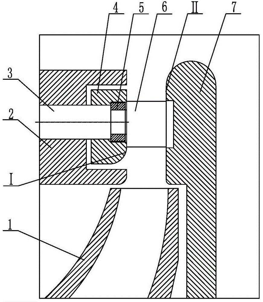
[0035] Such as figure 1 As shown, the adjustable diffuser proposed in this embodiment includes a stationary diffuser 7 , a movable diffuser 4 and a movable diffuser fixing device 2 for fixing the movable diffuser 4 . The guide rod 3 passes through the installation hole provided on the moving diffuser fixing device 2 and the through hole on the moving diffuser 4 in turn, and the locking device cooperates with the guide rod 3 to connect the moving diffuser 4 to the moving diffuser. The fixtures 2 are held together. In this embodiment, the moving diffuser 4 and the moving diffuser fixing device 2 are fixed together, which means that after the two are installed, the relative positions of the two are fixed, and no offset occurs. The locking device in this embodiment is a lock nut 5 , and the front end of the corresponding guide rod 3 is provided with threads, and the guide rod 3 and the lock nut 5 are threadedly connected.

[0036] The guide rod 3 can move along the depth directi...

Embodiment 2

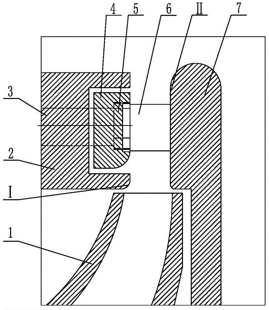
[0044] Such as image 3 As shown, it is the adjustable diffuser proposed in this embodiment, which is the same as the adjustable diffuser in Embodiment 1. The adjustable diffuser in this embodiment also includes a static diffuser 7, a moving A diffuser 4 and a moving diffuser fixing device 2 for fixing the moving diffuser 4 . The guide rod 3 passes through the installation hole provided on the moving diffuser fixing device 2 and the through hole on the moving diffuser 4 in turn, and the locking device cooperates with the guide rod 3 to connect the moving diffuser 4 to the moving diffuser. The fixtures 2 are held together. The locking device is a lock nut 5, and the front end of the corresponding guide rod 3 is provided with threads, and the guide rod 3 and the lock nut 5 are threadedly connected. The guide rod 3 can move along the depth direction of the installation hole on the moving diffuser fixing device 2 and the through hole on the moving diffuser 4 to adjust the distan...


PUM


Abstract

The invention relates to a diffuser structure, and discloses an adjustable diffuser. The adjustable diffuser comprises a static diffuser, a dynamic diffuser and a dynamic diffuser fixing device. A guide rod sequentially penetrates a mounting hole arranged on the dynamic diffuser fixing device and a through hole arranged on the dynamic diffuser. A locking device is matched with the guide rod to fix the dynamic diffuser and the dynamic diffuser fixing device together. The guide rod can move along the depth direction of the mounting hole and the through hole, so that the distance between the dynamic diffuser and the static diffuser is adjusted. Air exhausted by an impeller is sent in the position between the static diffuser and the dynamic diffuser. According to the adjustable diffuser, the guide rod drives the dynamic diffuser to move so that the distance between the dynamic diffuser and the static diffuser can be adjusted, the sectional area between the dynamic diffuser and the static diffuser can be changed, the surge phenomenon caused by the backflow of fluid in a flow channel under the low-load condition can be effectively improved, the operation range of a compressor can be widened, and the working energy efficiency of the compressor can be improved.

Description

technical field [0001] The invention relates to the field of diffuser structure, and more specifically discloses an adjustable diffuser which is installed on a centrifugal compressor and can widen the operating range of the centrifugal compressor. Background technique [0002] When the existing centrifugal compressors on the market are operated under the condition of light load, the gas in the flow channel is prone to backflow phenomenon, thus causing the deterioration of the gas flow condition. When the above phenomenon develops further and the pressure at the outlet of the compressor cannot meet the back pressure requirement, the flow rate of the compressor will decrease, and the gas at the outlet of the compressor will flow back into the compressor. As the gas flows back into the compressor, the back pressure of the compressor decreases, the flow rate of the compressor begins to increase again, the flow of the gas in the compressor improves, and the gas can be discharged ...

Claims


Application Information

Patent Timeline
Patent Type & Authority Applications(China)
IPC IPC(8): F04D29/44
CPCF04D29/444
Inventor 张治平钟瑞兴黄保乾蒋楠刘建飞将彩云陈玉辉谢蓉周义张竞
Owner GREE ELECTRIC APPLIANCES INC
Why Eureka
Try Eureka