
Continuously speed-variable fan silicone oil clutch with adjustable temperature region

A silicon oil clutch and continuously variable transmission technology, which is applied to clutches, fluid clutches, machines/engines, etc., can solve problems such as high manufacturing costs and poor product versatility, and achieve energy consumption reduction, ingenious structure, and extended interval time Effect

Active Publication Date: 2015-04-22
XUELONG GRP
View PDF8 Cites 1 Cited by
  • Summary
  • Abstract
  • Description
  • Claims
  • Application Information

AI Technical Summary

Problems solved by technology

[0003] The current silicone oil fan clutch can control the fan to rotate at two speeds. According to different ambient temperatures, the fan speed is different, and the difference in fan speed is determined by the amount of silicone oil output, so there will be a large output on the clutch. The opening and closing of the oil hole and the small oil hole, the large oil hole and the small oil hole determine the speed at which the fan works, and the opening and closing of the large oil hole and the small oil hole are controlled by the rotation of the valve plate Yes, in the initial state of the valve plate, both the large oil outlet hole and the small oil outlet hole are sealed. The distance between the oil outlet hole and the large oil outlet hole is constant, so the temperature corresponding to the two speeds is also constant, and the temperature range between the two will not change, but it is applied to different types of vehicles, and the temperature of the engine The heat dissipation requirements are different, and it is often necessary to change the temperature range, which requires re-opening the mold to adjust the distance between the small oil outlet hole and the large oil outlet hole. Such a product requires many molds, high manufacturing costs, and product versatility. Not strong

Method used


Image

  • Continuously speed-variable fan silicone oil clutch with adjustable temperature region
  • Continuously speed-variable fan silicone oil clutch with adjustable temperature region
  • Continuously speed-variable fan silicone oil clutch with adjustable temperature region

Examples


Embodiment 1

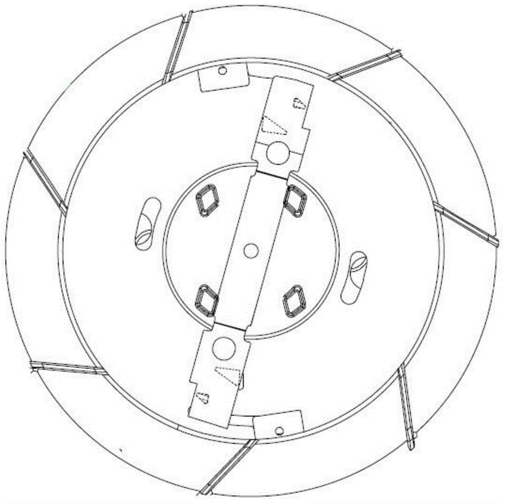
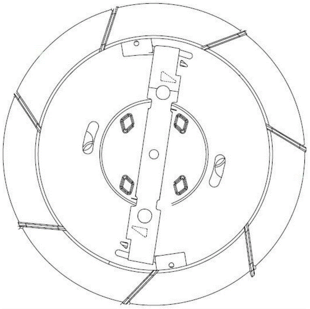
[0026] Such as figure 2 As shown, in the initial state, both ends of the valve plate 6 seal the large oil outlet hole 3 and the small oil outlet hole 4. When the temperature reaches 50°C, the valve plate 6 starts to rotate counterclockwise slowly. 5, the small oil outlet hole 4 is opened early at first, and the small oil outlet hole 4 is a right triangle. When opening, the opening area gradually increases until the small oil outlet hole 4 is fully opened, at which time the temperature has risen to 60 °, the speed of the fan is also gradually increased until it reaches 1800rpm, so that the fan enters the first-level speed rotation (such as image 3 , 5 shown);

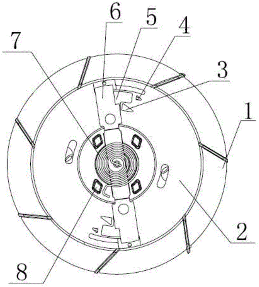
[0027] Such as figure 1 As shown, in the next rotation process, the temperature continues to rise, the valve plate 6 also continues to rotate, and the large oil outlet hole 3 is also a right triangle. The oil outlet hole 3 slides along the mouth, and the opening area of ​​the large oil outlet hole 3 gradually incr...

Embodiment 2

[0030] Such as figure 2 As shown, in the initial state, both ends of the valve plate 6 seal the large oil outlet hole 3 and the small oil outlet hole 4. When the temperature reaches 50°C, the valve plate 6 starts to rotate counterclockwise slowly. 5, the small oil outlet hole 4 is opened early at first, and the small oil outlet hole 4 is a right triangle. When opening, the opening area gradually increases until the small oil outlet hole 4 is fully opened, at which time the temperature has risen to 60 °, the speed of the fan is also gradually increased until it reaches 1800rpm, so that the fan enters the first-level speed rotation (such as image 3 , 5 shown);

[0031] Such as figure 1As shown, in the next rotation process, the temperature continues to rise, the valve plate 6 also continues to rotate, and the large oil outlet hole 3 is also a right triangle. The oil outlet hole 3 slides along the mouth, and the opening area of ​​the large oil outlet hole 3 gradually incre...


PUM


Abstract

The invention relates to a continuously speed-variable fan silicone oil clutch with an adjustable temperature region. The continuously speed-variable fan silicone oil clutch comprises a housing, a driven plate and a valve plate, wherein the driven plate is arranged in the middle of the front end surface of the housing; the front end surface of the driven plate is tightly adhered with the valve plate rotating around the center in an anticlockwise manner; a pair of large oil outlets is symmetrically formed around the center in the front surface of the driven plate; small oil outelts are formed in a position, close to the edge of the driven plate, at one side of the clockwise direction; the large oil outlets and the small oil outlets are sealed and sequentially opened in a rotary process; rectangular notches are formed in positions, corresponding to the small oil outlets, in one side reverse to the rotary direction in the two ends of the valve plate. The continuously speed-variable fan silicone oil clutch is simple in structure; the small oil outlets are opened in advance through the small oil outlets, so that primary-stage rotation speed is reached in advance, interval time between the primary-stage rotation speed and the secondary-stage rotation speed is prolonged, a temperature region between the two rotation speeds is expanded, the service life of an engine is prolonged, and remarkable effects of saving energy and reducing noises are achieved.

Description

technical field [0001] The invention relates to the field of automobile fan clutches, in particular to a continuously variable fan silicone oil clutch with adjustable temperature range. Background technique [0002] The silicone oil fan clutch uses silicone oil as a medium to transmit torque by utilizing the high viscosity of silicone oil. Using the temperature of the air behind the radiator, the disengagement and engagement of the fan clutch is automatically controlled by a temperature sensor. When the temperature is low, the silicone oil returns to the oil storage chamber, the fan clutch is disengaged, and the fan speed slows down, basically idling. When the temperature is high, the viscosity of the silicone oil makes the fan clutch engage, so the fan and the water pump shaft rotate together to regulate the temperature of the engine. [0003] The current silicone oil fan clutch can control the fan to rotate at two speeds. According to different ambient temperatures, the ...

Claims


Application Information

Patent Timeline
Patent Type & Authority Applications(China)
IPC IPC(8): F16D35/00F01P7/04
Inventor 贺频艳贺群艳虞宁张文辉虞雷斌俞豪杰竺菲菲
Owner XUELONG GRP
Learn More