ADSS optical cable air-connection box

A splice box, optical cable technology, applied in the field of ADSS optical cable installation, can solve the problem of inability to complete the mechanical connection of two optical cables

Inactive Publication Date: 2015-04-22
STATE GRID CORP OF CHINA +1
View PDF8 Cites 4 Cited by
  • Summary
  • Abstract
  • Description
  • Claims
  • Application Information

AI Technical Summary

Problems solved by technology

[0003] There is also a kind of horizontal joint box used to connect ordinary optical cables, which is also sometimes used on ADSS optical cables, but it cannot be stressed, and it is also fixed on the tower. These joint boxes cannot be used to connect ADSS optical cables in the air. The mechanical connection of an optical fiber cable in the air can only achieve the optical connection between the optical fiber cores in the cable; in power engineering, wires and ground wires can be connected in the air, but optical cables can only be connected on the tower. The main reason is that there is no suitable splice box that can be used to connect optical cables in the air

Method used


Image

  • ADSS optical cable air-connection box
  • ADSS optical cable air-connection box
  • ADSS optical cable air-connection box

Examples


Embodiment 1

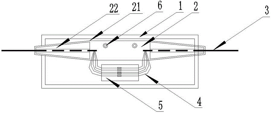
[0023] When the gear distance is between 100m and 300m, the force receiving body 2 includes an outer shell 21 and a shuttle-shaped clamp 22. The outer shell 21 is a hollow shell with a columnar structure in the middle and symmetrical tapered ends at both ends. , the shuttle-shaped clamp 22 is two and symmetrically arranged in the tapered cavity of the outer shell, its structure is compatible with the tapered cavity, the shuttle-shaped clamp 22 is composed of several shuttle-shaped bodies, so The shuttle-shaped bodies are evenly distributed around the central axis of the outer casing 21 to form an optical cable channel, gaps are left between the shuttle-shaped bodies, and wear-resistant bushings are provided on the inner surface of the optical cable channel.

[0024] Preferably, the outer casing 21 is made of high-strength aluminum alloy, and the shuttle clamp 22 is made of weather-resistant engineering plastics.

[0025] After the optical cable 3 penetrates, the shuttle clamp ...

Embodiment 2

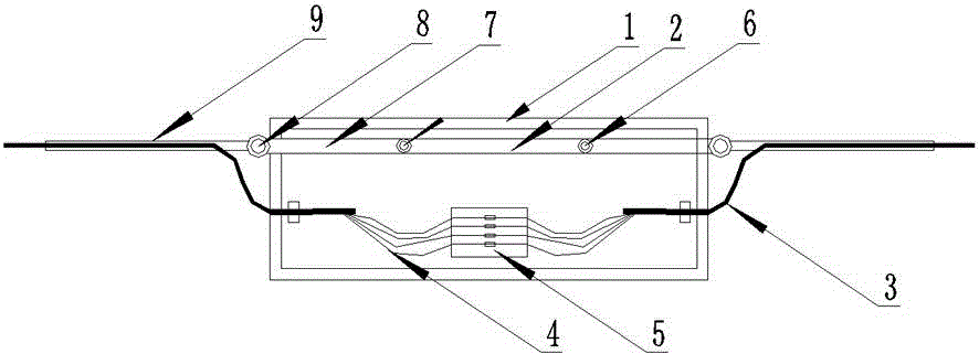
[0027] When the gear distance is greater than 300 meters, the stressed body 2 includes a rod body 7, a circular hanging ring 8 and a pre-twisted wire 9. The rod body 7 is a rod-shaped structure, and its two ends extend to the outside of the box body 1. The circular hanging rings 8 are arranged symmetrically at both ends of the rod body 7, and are respectively movably connected with the pre-twisted wires 9, and the pre-twisted wires 9 hold the terminals of the two optical cables 3 respectively.

[0028] Preferably, the rod body 7 is made of high-strength aluminum alloy.

[0029] During use, two pre-twisted wires 9 are respectively held to hold two optical cables 3, and then the pre-twisted wires 9 are hung on the circular hanging ring 8, so that the left and right two optical cables 3 are connected through the rod body 7, thereby realizing Stress; Wherein, the pre-twisted wire 9 can select different models according to the gauge distance and the outer diameter of the optical ca...


PUM


Abstract

The invention relates to an ADSS optical cable air-connection box, belongs to the technical field of ADSS optical cable installation, and aims at providing the ADSS optical cable air-connection box that can used for ADSS cable air connection. An original stretching resistance of a cable can be maintained in the connection point after connection, the diameter of a cable channel is variable, the ADSS optical cable air-connection box can be adapted to cables of different external diameters, and two optical cables which cannot realize butt joint due to the lengths can be connected via a double-box structure. The ADSS optical cable air-connection box comprises a box body, a bearing body and a fiber fusion disk, wherein the box includes a hollow casing, the bearing body and the fiber fusion disk are fixed in the box, the cables are tightened by the bearing body, fibers of two optical cables are welded via the fiber fusion disk and the bearing body is fixed in the box via fasteners. The air-connection box can be widely applied to the technical field of ADSS optical cable installation.

Description

technical field [0001] The invention discloses an ADSS optical cable aerial splice box, belonging to the technical field of ADSS optical cable installation. Background technique [0002] At present, there is basically only one type of intermediate splice box used to connect ADSS self-supporting optical cables, which is a common cap splice box made of aluminum alloy or non-metal; Fasteners are hung on the pole tower, and the optical cables on both sides are also fixed on the pole tower with tension-resistant hardware. The splice box itself is not subject to the tension of the optical cable, and it itself has no force-bearing parts. [0003] There is also a kind of horizontal joint box used to connect ordinary optical cables, which is also sometimes used on ADSS optical cables, but it cannot be stressed, and it is also fixed on the tower. These joint boxes cannot be used to connect ADSS optical cables in the air. The mechanical connection of an optical fiber cable in the air ...

Claims


Application Information

Patent Timeline
Patent Type & Authority Applications(China)
IPC IPC(8): G02B6/44
CPCG02B6/4446G02B6/255G02B6/4454
Inventor 张宇刘学明张星杨斌慕文源赵宇枢
Owner STATE GRID CORP OF CHINA
Why Eureka
Try Eureka