Brush type direct current electromagnetic stirring cup

An electromagnetic stirring and brush-type technology, which is applied in household utensils, applications, kitchen utensils, etc., can solve the problems of complicated cleaning process of cups, incomplete daily cleaning of cups, dirt and slits in threaded joints, etc., and achieves convenient cleaning Thorough, convenient and fast charging, not easy to hide dirt

Inactive Publication Date: 2015-04-29
祁高鹏
View PDF9 Cites 4 Cited by
  • Summary
  • Abstract
  • Description
  • Claims
  • Application Information

AI Technical Summary

Problems solved by technology

[0003] In the prior art, since the motor shaft rotates, the sealing material will be worn, and gaps will be formed after the sealing material is worn, the sealing effect will be reduced, and the substances in the cup will penetrate into the bottom of the cup to cause pollution of the substances in the cup, bringing safety hazards, and even the cup The substance infiltrated into the motor and caused damage to the motor, resulting in a short service life of the mixing cup
At the same time, the motor shaft and stirring blade fixed on the bottom of the cup in the prior art bring about a dead angle for cleaning, resulting in incomplete daily cleaning of the cup
[0004] Now there are patents to improve this. The integrated design of the cup bottom and the cup body is improved so that the cup bottom and the cup body are connected by threads, so that the cup bottom and the cup body can be separated and cleaned. This solution can be enhanced to a certain extent. The cleaning effect of the electric mixing cup, but it also makes the cleaning process of the cup more complicated, and there are slits where dirt is hidden at the threaded connection, causing sanitary hazards

Method used


Image

  • Brush type direct current electromagnetic stirring cup
  • Brush type direct current electromagnetic stirring cup
  • Brush type direct current electromagnetic stirring cup

Examples


Embodiment Construction

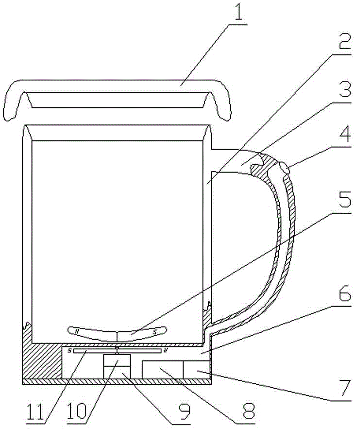
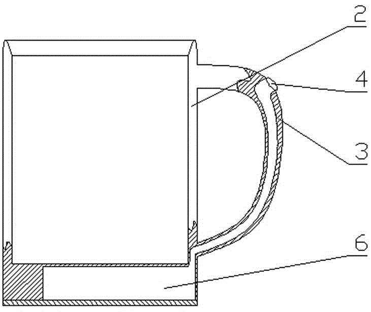
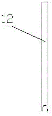
[0022] The specific implementation, structure, features and effects of the brushed DC electromagnetic stirring cup according to the present invention will be described in detail below in conjunction with the accompanying drawings and preferred embodiments.

[0023] see Figure 1 to Figure 3 , the brush type DC electromagnetic stirring cup of the present invention comprises a cup cover 1, a cup body 2, a permanent magnet blade 5, a driving part, and a cup cover 1 is installed on the top of the cup body 2, wherein: the bottom of the cup body 2 and the cup handle 3 A cavity 6 is arranged in communication between them, and the cavity 6 is equipped with a power supply part, a driving part and electric wires connecting each part, and the permanent magnet blade 5 is arranged in the cup body 2 . The power supply part is composed of a charging device 7 and a storage battery 8, and the charging interface of the charging device 7 is a Micro USB interface. The drive part includes a motor...


PUM


Abstract

The invention discloses a brush type direct current electromagnetic stirring cup which comprises a cup cover (1), a cup body (2), permanent magnet blades (5) and a driving part, wherein the cup cover (1) is arranged at the top of the cup body (2); the brush type direct current electromagnetic stirring cup is characterized in that a cavity (6) is communicated between the bottom of the cup body (2) and a cup grip (3); a power supply part, the driving part and wires connected with all parts are arranged in the cavity (6); the permanent magnet blades (5) are arranged in the cup body (2); the driving part comprises a motor (9), a speed adjustment device (10), a strong magnetic rotary sheet (11) and a speed adjustment switch (4); the motor (9) is arranged at the bottom of the cavity (6); the speed adjustment device (10) is arranged above the motor (9); the upper part of the speed adjustment device (10) is connected with the strong magnetic rotary sheet (11); the strong magnetic rotary sheet (11) is arranged right below the permanent magnet blades (5); the speed adjustment switch (4) is arranged at the upper part of the cavity (6) of the cup grip (3). The brush type direct current electromagnetic stirring cup is safe, durable, low in cost and practical and can be cleaned thoroughly.

Description

technical field [0001] The invention belongs to the technical field of cups for daily use, and in particular relates to a brushed DC electromagnetic stirring cup. Background technique [0002] The electric stirring cup drives the DC motor through direct current, and the motor drives the stirring blades to stir the contents of the cup. Common electric stirring cups are generally equipped with a DC motor at the bottom, and the motor shaft passes through the hole at the bottom of the cup to drive a stirring blade to rotate in the container to stir the contents of the cup. There must be a seal between the cup and the motor shaft to prevent the contents of the cup from escaping. The sealing method is to use the elasticity of the sealing material itself to tightly compress the motor shaft to achieve the sealing effect. [0003] In the prior art, since the motor shaft rotates, the sealing material will be worn, and gaps will be formed after the sealing material is worn, the seali...

Claims


Application Information

Patent Timeline
Patent Type & Authority Applications(China)
IPC IPC(8): A47J43/07A47J43/046
Inventor 祁高鹏
Owner 祁高鹏
Why Eureka
Try Eureka