Mask

A face mask and face technology, applied in the direction of breathing masks, breathing masks, medical science, etc., can solve the problem of not being able to ensure exhaled air

Active Publication Date: 2015-04-29
NIHON KOHDEN CORP
View PDF7 Cites 9 Cited by
  • Summary
  • Abstract
  • Description
  • Claims
  • Application Information

AI Technical Summary

Problems solved by technology

Due to this difference in facial shape, it is generally not possible to ensure that the exhaled air of the subject is introduced into the exhaled air concentration detection sensor

Method used


Image

  • Mask
  • Mask
  • Mask

Examples


Embodiment Construction

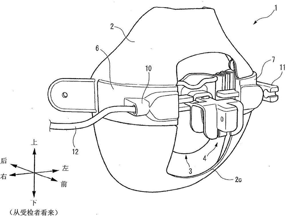
[0031] Exemplary embodiments of the present invention will now be described in detail with reference to the accompanying drawings. The terms "right" and "left" as used herein refer to right and left directions, respectively, as seen from a subject wearing the mask.

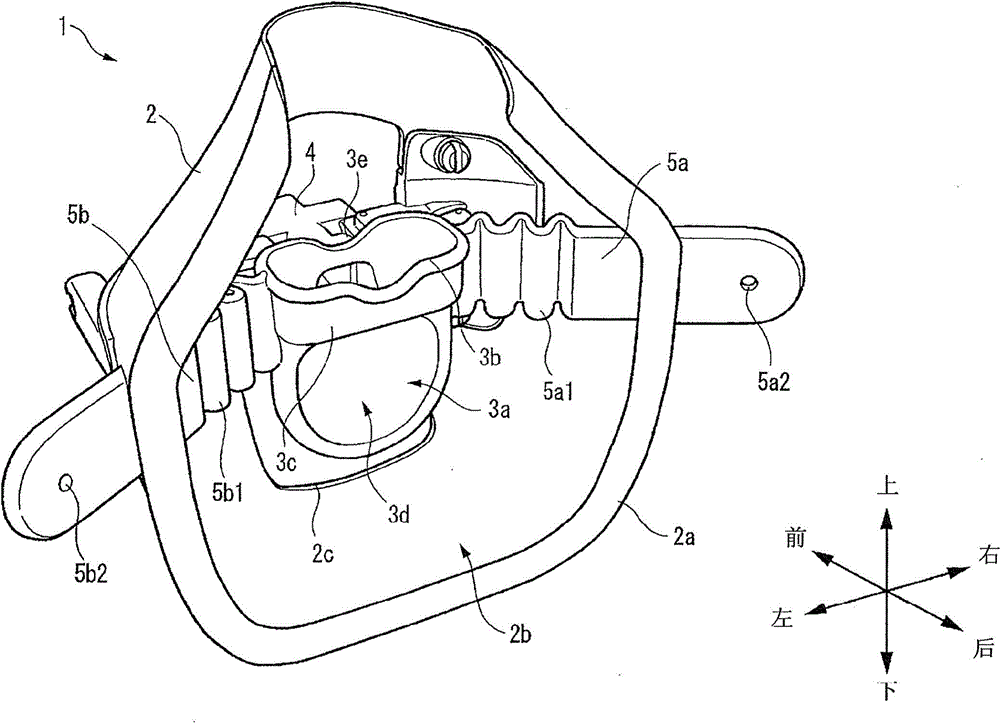
[0032] figure 1 is a perspective view showing the appearance of the mask 1 according to the embodiment of the present invention when viewed obliquely from the front right side thereof. figure 2 is a perspective view showing the appearance of the mask 1 when viewed obliquely from the left rear side thereof. A mask 1 to be attached to a subject's face includes a wall portion 2 , an exhaled gas introduction portion 3 and a vent portion 4 .

[0033] The wall portion 2 is formed in a dome-shaped appearance made of elastic material. The wall portion 2 has a size and shape to cover at least part of the subject's nose and mouth. An edge portion 2a on the rear side of the wall portion 2 contacts the subject's face. T...


PUM


Abstract

A mask configured to be attached to the face of a subject includes a wall section that defines an internal space and covers at least a portion of a nose and a mouth of the subject, an expired gas introduction section that is disposed in the internal space and introduce the subject's expired gas, and a communication section defining a communication channel through which the subject's expired gas introduced from the expired gas introduction section is introduced into an expired gas concentration detection sensor. The position of the expired gas introduction section in the internal space is variable.

Description

Background technique [0001] The present invention relates to a mask attached to the face of a subject so as to direct the exhaled air of the subject to an exhaled air concentration detection sensor. [0002] As an example of such a mask, Patent Document 1 discloses an oxygen mask including a wall portion, an exhaled gas introduction portion, and a vent portion. The wall portion defines an interior volume of the mask so as to cover at least a portion of the subject's nose and mouth. The exhaled gas introduction part is arranged in the inner space so as to introduce the exhaled gas of the subject. The ventilation portion defines a ventilation channel supported by the wall portion, and the subject's exhaled gas is introduced into the exhaled gas concentration detection sensor through the ventilation channel. [0003] [Patent Document 1] JP-A-2011-115543 [0004] The shape of the face to which such a mask is attached is different for each subject. Specifically, the shape of th...

Claims


Application Information

Patent Timeline
Patent Type & Authority Applications(China)
IPC IPC(8): A61M16/06
CPCA61B5/083A61B5/6819A61B5/682A61B5/097A61B5/6803A61M16/06A62B18/02A61M16/1005A61M2205/3313A61M2230/432A61M16/085A61M16/0683A61M16/0605A61M2205/0216A61M2205/502A61M2205/3584A61M2202/0208A62B18/006A62B7/10A62B9/04A62B9/006A62B18/08A61M2202/0007A61B5/082A61M16/0003A61M2016/103A61B5/0833A61B5/0873
Inventor 井上正行
Owner NIHON KOHDEN CORP
Why Eureka
Try Eureka