Tool magazine tool clamping device

A clamping device and cutting tool technology, applied in the direction of positioning device, clamping, manufacturing tools, etc., to achieve the effect of reducing self-weight, reducing damage, and ensuring assembly requirements

Inactive Publication Date: 2015-04-29
HUBEI YIXING INTELLIGENT EQUIP CO LTD
View PDF6 Cites 12 Cited by
  • Summary
  • Abstract
  • Description
  • Claims
  • Application Information

AI Technical Summary

Problems solved by technology

But it still does not solve the problem of affecting the assembly accuracy of the clamping device due to the collision between the tool and the clamping device

Method used


Image

  • Tool magazine tool clamping device
  • Tool magazine tool clamping device

Examples


Embodiment Construction

[0016] Below in conjunction with accompanying drawing and specific embodiment the present invention is described in further detail:

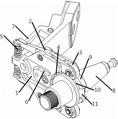
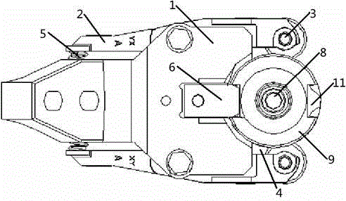
[0017] see Figure 1-Figure 2 , a tool magazine clamping device, including a clamping seat 1, the upper and lower ends of the clamping seat 1 are symmetrically provided with a lever mechanism 2, the lever mechanism 2 is fixed on the clamping seat 1 by bolts, one end of the lever mechanism 2 A roller 3 is installed, and a holder groove 4 is formed between the roller 3 and the holder 1, and a spring 5 is installed on the holder 1, and the spring 5 is located between the lever mechanisms 2 and is fixedly connected with the lever mechanism 2 , and the spring 5 and the roller 3 are not located at the two ends of the lever mechanism 2, the clamp seat 1 is provided with a limit block 6, and the limit block 6 extends into the clamp seat groove 4.

[0018] The clamping base 1 is made of aluminum material and is in an "L" shape as a whole. The clamping b...


PUM


Abstract

The invention relates to a tool magazine tool clamping device comprising a clamping seat. Lever mechanisms are arranged at the upper end and the lower end of the clamping seat symmetrically, each lever mechanism is fixed on the clamping seat through bolts, a roller is mounted at one end of the lever mechanism, and a clamping seat groove is formed among the rollers and the clamping seat. The tool magazine tool clamping device is characterized in that a spring is mounted on the clamping seat, located between the lever mechanisms and fixedly connected with the lever mechanisms, and the spring and the rollers are located at two ends of the lever mechanism respectively. The spring is arranged between the lever structures, collision force between the clamping seat and a tool is buffered through the spring during tool changing, so that damage to the clamping seat due to tool changing collision is reduced, service life of the clamping seat is prolonged, and frequency of maintenance of the clamping seat is lowered.

Description

technical field [0001] The invention relates to the field of mechanical equipment, in particular to a tool clamping device for a tool magazine. Background technique [0002] When machining parts in drilling and tapping centers, it is necessary to replace different tools from the tool magazine. As a tool clamping device in the tool change of the tool magazine, it is very important. In the traditional machining center tool changing device, the entire tool magazine moves toward the tool during the tool change. The main shaft moves, and when the tool on the main shaft enters the clamping slot of the tool magazine, the main shaft moves upwards to break away from the tool, and the tool magazine rotates at this moment. When the tool to be changed is aligned directly below the main shaft, the main shaft moves down, so that the tool enters the taper hole of the main shaft from the clamping device slot, and after the tool is clamped, the tool magazine returns to its original position....

Claims


Application Information

Patent Timeline
Patent Type & Authority Applications(China)
IPC IPC(8): B23Q3/157
CPCB23Q3/157B23Q2003/15527
Inventor 汪军
Owner HUBEI YIXING INTELLIGENT EQUIP CO LTD
Why Eureka
Try Eureka