Check patentability & draft patents in minutes with Patsnap Eureka AI!

Pressurizing mechanism of hydraulic vulcanizing machine

A technology for pressurizing mechanism and vulcanizing machine, which is applied in the field of pressurizing mechanism and hydraulic vulcanizing machine, which can solve the problems of affecting work efficiency, small space occupation, and narrow space of vulcanizing machine, so as to improve disassembly and assembly efficiency and efficiency Improved effect

Active Publication Date: 2015-04-29
SINO ARP TIRES EQUIP TECH (SUZHOU) CO LTD
View PDF5 Cites 0 Cited by
  • Summary
  • Abstract
  • Description
  • Claims
  • Application Information

AI Technical Summary

Problems solved by technology

figure 1 Shown is the structure of the pressurizing mechanism of a hydraulic vulcanizing machine commonly used now. The hollow cylinder 1 is generally used in the pressurizing mechanism now. The upper and lower ends of the piston 11 of the hollow cylinder 1 are provided with upper snap rings 12 and The lower snap ring 13, the advantage of the pressurizing mechanism of this structure at present is that it takes up less space, and the disadvantage is that it is inconvenient to install and disassemble the lower rod 2. This is because when disassembling the lower rod 2, it first needs to be disassembled Drop the hollow oil cylinder 1, and then remove the upper snap ring 12 to pull out the lower rod 2
This inconvenience is particularly evident in the field of use. Because the space where the vulcanizer is placed is generally narrow and the pressurized oil cylinder is relatively heavy, lifting tools cannot be used. In order to ensure positioning accuracy and personnel safety, special tools must be used to disassemble. , greatly affect work efficiency

Method used


Image

  • Pressurizing mechanism of hydraulic vulcanizing machine
  • Pressurizing mechanism of hydraulic vulcanizing machine

Examples


Embodiment Construction

[0018] Preferred embodiments of the present invention will be described in detail below in conjunction with the accompanying drawings.

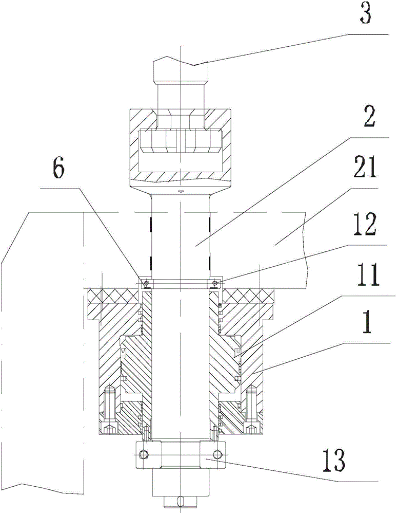
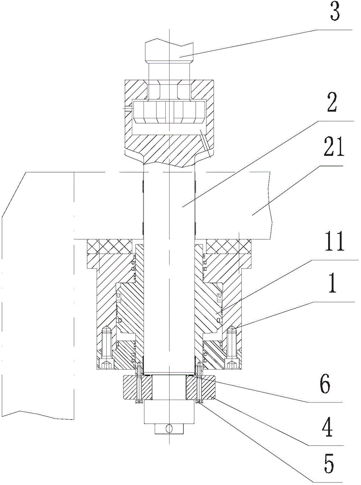
[0019] In order to achieve the purpose of the present invention, as figure 2 As shown, in some embodiments of the pressurizing mechanism of the hydraulic vulcanizer of the present invention, a hollow cylinder 1 is included, the piston 11 of which is sleeved on the lower rod 2 of the hydraulic vulcanizer, and the lower rod 2 is connected with the upper rod 3. The upper end of the piston 11 approaches or touches the base 21 of the hydraulic vulcanizer without hindrance, that is, it is close to the base 21 or directly contacts the base 21. The lower end of the piston 11 is provided with a snap ring 4, and the snap ring 4 is fixedly sleeved on the pull-down rod 13. , while the snap ring 4 is also fixedly connected to the piston 11 by screwing.

[0020] Compared with the structure in the background technology, this mechanism cancels the upper sn...


PUM


Abstract

The invention discloses a pressurizing mechanism of a hydraulic vulcanizing machine. The pressurizing mechanism comprises a hollow oil cylinder, wherein a piston of the hollow oil cylinder is arranged on a lower pull rod of the hydraulic vulcanizing machine in a sleeving manner, the upper end part of the piston accessibly approaches or contacts with a base of the hydraulic vulcanizing machine, and a snap ring is arranged at the lower end part of the piston, fixedly arranged on the lower pull rod in a sleeving manner and is fixedly connected with the piston. Compared with the prior art, the dismounting and mounting efficiency of the lower pull rod can be increased effectively, so that the working efficiency of the lower pull rod and the pressurizing mechanism can be increased.

Description

technical field [0001] The invention relates to a pressurizing mechanism in the field of tire vulcanizing equipment, in particular to a pressurizing mechanism of a hydraulic vulcanizing machine. Background technique [0002] The pressurizing mechanism is a device applied to the pull rod of the tire vulcanizer, and its function is to provide the driving force for the upward movement of the pull rod when the upper and lower pull rod is clamped. figure 1 Shown is the structure of the pressurizing mechanism of a hydraulic vulcanizing machine commonly used now. The hollow cylinder 1 is generally used in the pressurizing mechanism now. The upper and lower ends of the piston 11 of the hollow cylinder 1 are provided with upper snap rings 12 and The lower snap ring 13, the advantage of the pressurizing mechanism of this structure at present is that it takes up less space, and the disadvantage is that it is inconvenient to install and disassemble the lower rod 2. This is because when ...

Claims


Application Information

Patent Timeline
IPC IPC(8): B29C35/00B29L30/00
Inventor 廖建忠
Owner SINO ARP TIRES EQUIP TECH (SUZHOU) CO LTD
Features
  • R&D
  • Intellectual Property
  • Life Sciences
  • Materials
  • Tech Scout
  • Unparalleled Data Quality
  • Higher Quality Content
  • 60% Fewer Hallucinations
Learn More