Gravure printing plate, manufacturing method thereof, gravure printing machine, and manufacturing method for laminated ceramic electronic component

A manufacturing method and gravure printing technology, applied in the direction of electrical components, multilayer capacitors, printing, etc., can solve the problems of reduced opening area, easy residual conductive paste, narrowing of the internal electrode area, etc., to reduce the degree of unevenness Effect

Active Publication Date: 2015-04-29
MURATA MFG CO LTD
View PDF12 Cites 2 Cited by
  • Summary
  • Abstract
  • Description
  • Claims
  • Application Information

AI Technical Summary

Problems solved by technology

However, if the gap 10 is further enlarged to further enlarge the width of the frame-shaped concave portion 11, there will be a problem that the required thickness cannot be obtained near the outline 6 of the conductive paste film 5a.
[0020] However, in the above gravure cylinder 1b, the amount of conductive paste that can be filled in the peripheral cells 8 is reduced.
In addition, in the peripheral cells 8, the opening area with respect to the depth of the cells is reduced, and the conductive paste tends to remain in the cells during transfer.
As a result, as in the case of the gravure cylinder 1a shown in FIG. 17 , there is a problem that a desired thickness cannot be obtained near the contour of the conductive paste film.
[0021] As mentioned above, if it is difficult to ensure the required thickness in the vicinity of the outline of the conductive paste film, the following problems will occur: in the firing process that is a subsequent process for manufacturing laminated ceramic electronic components, for example, there will be The metal powder near the outline of the conductive paste film will burn off, and the area of ​​the internal electrodes will be narrowed
As a result, in multilayer ceramic capacitors, for example, the desired capacitance cannot be obtained

Method used


Image

  • Gravure printing plate, manufacturing method thereof, gravure printing machine, and manufacturing method for laminated ceramic electronic component
  • Gravure printing plate, manufacturing method thereof, gravure printing machine, and manufacturing method for laminated ceramic electronic component
  • Gravure printing plate, manufacturing method thereof, gravure printing machine, and manufacturing method for laminated ceramic electronic component

Examples


Embodiment Construction

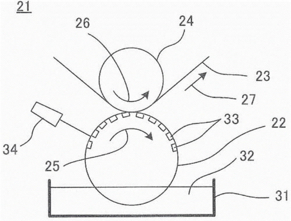
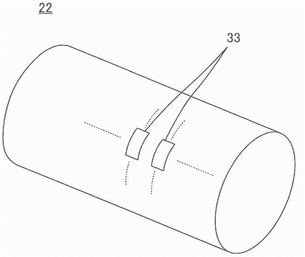
[0068] Refer below figure 1 , the gravure printing machine 21 including the gravure cylinder 22 as the gravure printing plate according to the present invention will be briefly described.

[0069] The gravure printing machine 21 includes a gravure cylinder 22 and an impression cylinder 24 facing the gravure cylinder 22 with a sheet-like object 23 interposed therebetween. The gravure cylinder 22 and the impression cylinder 24 rotate in the directions of arrows 25 and 26 respectively, thereby conveying the object to be printed 23 in the direction of the arrow 27 . In addition, in the case of a gravure printing press, a gravure printing press without an impression cylinder may also be used.

[0070] The gravure printing machine 21 is used to manufacture multilayer ceramic electronic components such as multilayer ceramic capacitors. More specifically, the gravure printing machine 21 is used to form a paste film on the printed object 23 by gravure printing, and this paste film w...


PUM


Abstract

Banks, as well as a plurality of substantially recess-shaped cells defined by the banks, are provided in an image section formed in a gravure printing plate. Each of edge cells located along an outer edge of the image section is provided with a projecting portion that projects from a part of a base surface of that edge cell, and each projecting portion is distanced from the banks and located closer to the outer edge than the center of the corresponding edge cell. Preferably, the projecting portions and the banks that face the outer edge are positioned at a predetermined interval from the outer edge, and substantially frame-shaped recess portions that extend continuously along the outer edge are provided in the image section.

Description

technical field [0001] The present invention relates to a gravure printing plate, a method for manufacturing the same, a gravure printing machine, and a method for manufacturing laminated ceramic electronic components using a gravure printing machine, and in particular to a method for improving the contour accuracy of a paste film formed by gravure printing technology. Background technique [0002] In order to manufacture a multilayer ceramic electronic component such as a multilayer ceramic capacitor, for example, a step of forming a conductive paste film to be an internal electrode on a ceramic green sheet is performed. The internal electrodes formed from this conductive paste film are required to have high pattern accuracy and uniform thickness. Gravure printing is attracting attention as a technology capable of meeting this requirement. [0003] The gravure printing method is carried out using an intaglio cylinder (plate body) as a gravure printing plate, and is a prin...

Claims


Application Information

Patent Timeline
Patent Type & Authority Applications(China)
IPC IPC(8): B41N1/06B41C1/18H01G4/008H01G4/30
CPCH01G4/308B41C1/00B41C1/188B41N1/06B41N1/20H01G4/012H01G4/12
Inventor 吉田和宏
Owner MURATA MFG CO LTD
Why Eureka
Try Eureka