
A kind of tail dragging device of automobile

A technology of automobiles and hydraulic power devices, which is applied to vehicle parts, transportation and packaging, bumpers, etc., to achieve the effect of carrying safety and avoiding damage

Inactive Publication Date: 2016-06-29
ZHEJIANG YANTONG FURNITURE CO LTD
View PDF6 Cites 0 Cited by
  • Summary
  • Abstract
  • Description
  • Claims
  • Application Information

AI Technical Summary

Problems solved by technology

[0007] The purpose of the present invention is to provide a tail dragging device for a car in order to solve the defects in the prior art when the car carries a bicycle

Method used


Image

  • A kind of tail dragging device of automobile
  • A kind of tail dragging device of automobile
  • A kind of tail dragging device of automobile

Examples


Embodiment Construction

[0027] In order to have a further understanding and understanding of the structural features of the present invention and the achieved effects, the preferred embodiments and accompanying drawings will be used for a detailed description, as follows:

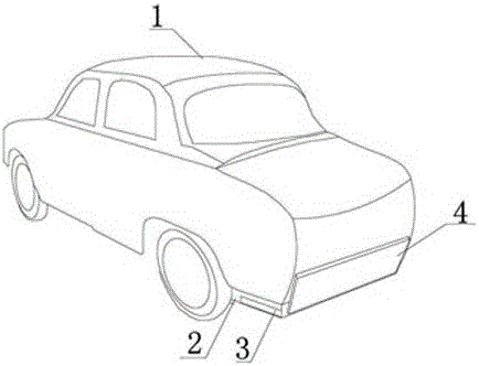
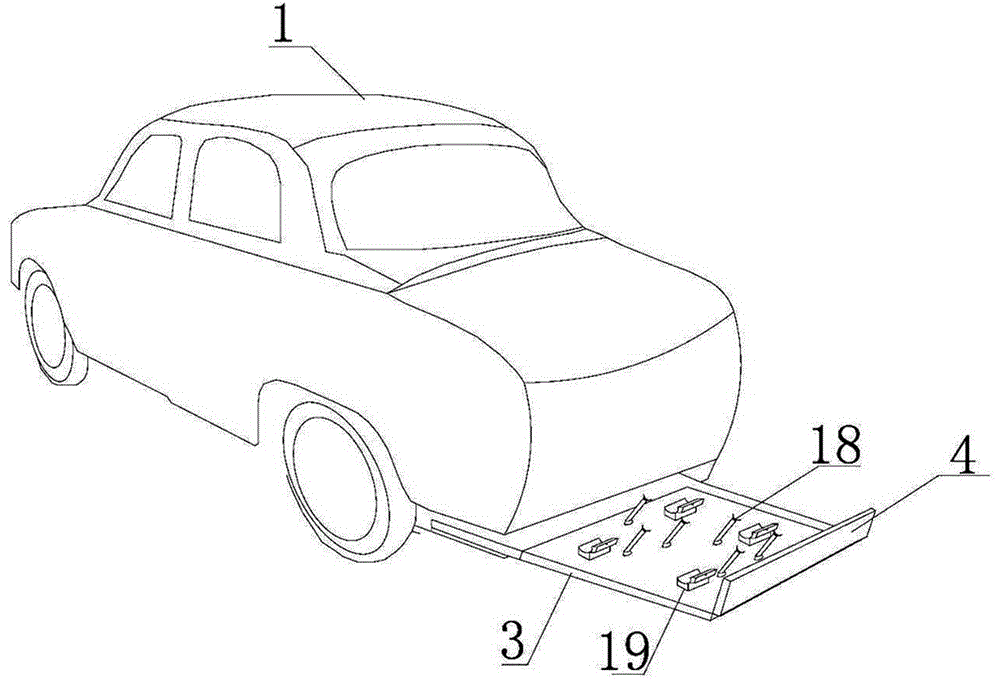
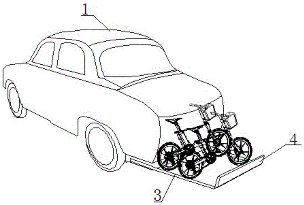
[0028] Such as Figure 1 to Figure 6 As shown, a tail dragging device of an automobile comprises a fixed plate 2 arranged under the tail of the automobile 1. The inside of the fixed plate 2 has a cavity, and a foldable drag plate is accommodated in the cavity. The board includes a relatively foldable slide plate 3 and a bumper baffle plate 4. There are guide rails 5 on both sides of the cavity of the fixed plate 2, and a roller 6 is provided under the slide plate 3, and the peripheral surface of the roller 6 is in contact with the guide rail 5; the slide plate 3 and The bottom joint of the fixed plate 2 is provided with a hydraulic power device, and the joint of the slide plate 3 and the bumper baffle 4 is provided with an electri...


PUM


Abstract

The invention relates to a vehicle tail carriage unit. The vehicle tail carriage unit comprises a fixed plate arranged on the lower portion of a vehicle tail. The fixed plate is provided with a cavity. A foldable carriage is accommodated in the cavity. The foldable carriage comprises a sliding plate foldable in half and a bumper baffle. The upper surface of the sliding plate is provided with a bicycle fixing device and comprises a plurality of support frames in sliding connection with the surface of the sliding plate and a bicycle tire fixing structure. The support frame can rotate relative to the sliding plate. The tire fixing structure comprises a fixed block fixed to the surface of the sliding plate and a movable block in rotation connection with the fixed block. The opposite surfaces of the fixed block and the movable block are provided with an arc-shaped groove matched with a bicycle tire. The free end of the movable block is provided with a fastener snapped to the fixed block. A bicycle can be placed on the sliding plate and fixed through the bicycle fixing device to be transported through a vehicle. The bumper baffle can play a protective role on the vehicle and the bicycle. By means of the vehicle tail carriage unit, the bicycle can be carried safely and easily.

Description

technical field [0001] The invention relates to a tail extension device of an automobile. Background technique [0002] Bicycles or electric vehicles are convenient and leisure means of transportation in our lives, and cars are also an important means of transportation for our travel and transportation. In order to achieve the purpose of both traveling and leisure, people usually carry bicycles in cars. Riding mountain bikes in the wild, enjoying the fun of leisure, the current cars generally carry bicycles by installing bicycle holders on the roof, but there are certain defects in this way of carrying bicycles: [0003] 1. It is inconvenient to install the bicycle fixing frame on the roof of the car, and it is cumbersome to install the fixing frame. When not in use, the bicycle fixing frame needs to be disassembled; [0004] 2. When the current car carries a bicycle, the bicycle needs to be placed on the top of the car, which cannot be done by short people; [0005] 3. No...

Claims


Application Information

Patent Timeline
Patent Type & Authority Patents(China)
IPC IPC(8): B60R9/10B60R9/06
CPCB60R9/06B60R9/10B60R19/48
Inventor 蔡钟坤
Owner ZHEJIANG YANTONG FURNITURE CO LTD
Learn More