Single-pedal speed control system of electric vehicle

A technology for speed control and electric vehicles, which is applied to electric vehicles, the layout of power plant control mechanisms, control and drive, etc., can solve the problems of increasing driver fatigue, increasing operation complexity, and reducing driving safety, so as to eliminate errors Possibility of operation, ease of driving technique, effect of ease of quick mastery

Inactive Publication Date: 2015-04-29
杨国青
View PDF9 Cites 30 Cited by
  • Summary
  • Abstract
  • Description
  • Claims
  • Application Information

AI Technical Summary

Problems solved by technology

[0003] First, the operation complexity is high
Driving this kind of electric vehicle needs to be familiar with the accelerator pedal and brake pedal at the same time. Learning to drive this kind of electric vehicle requires a long process, which is not conducive to quickly mastering driving skills
[0004] Second, it is easy to cause misuse
The problem with this solution is that the driver cannot perform emergency braking by increasing the pedaling force. On the contrary, when the pedal is released for braking, due to the inertia, the foot will naturally increase the pedaling force. At this time, it will enter the acceleration state instead, reducing the driving safety
Patent 02114368.4 adopts the method of binding the feet. The foot is pulled to control the accelerator, and the foot is stepped to control the brake. The operation is more complicated, and the long-term pulling state increases the fatigue of the driver and reduces the safety of driving.
Patent 97192004.4 also uses a purely mechanical control method, which requires a combination of multiple pedals to complete the operation, which increases the complexity of the operation

Method used


Image

  • Single-pedal speed control system of electric vehicle
  • Single-pedal speed control system of electric vehicle
  • Single-pedal speed control system of electric vehicle

Examples


Embodiment Construction

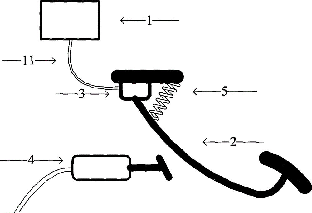
[0019] figure 1 1 is a speed controller, which uses single-chip technology to control the vehicle power motor. figure 1 2 is the speed control pedal through which the driver expresses his speed control intention. figure 1 The 3 represents the pedal position sensor, which is installed on the speed control pedal shaft to detect the position of the speed control pedal. figure 1 The 4 is the brake valve, which is connected to the brake disc through a hydraulic pipeline. figure 1 The 5 is the return spring, which pulls the speed control pedal to the initial position. figure 1 11 is the twisted pair cable connecting the speed controller to the pedal position sensor.

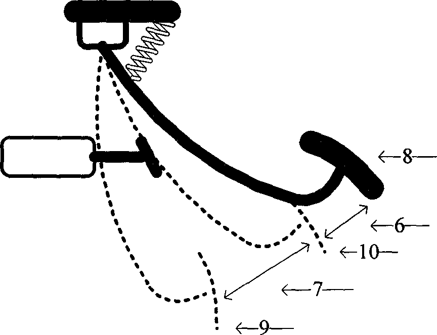
[0020] figure 2 The 6 is the speed adjustment zone. The speed control pedal is not in contact with the brake valve in the speed adjustment zone. At this time, the speed control pedal is used to control the speed of the power motor of the electric vehicle. figure 2 The 7 in the middle is the braking zone. The speed control ...


PUM


Abstract

The invention provides a single-pedal speed control system of an electric vehicle. The single-pedal speed control system comprises a speed control pedal, a pedal position sensor, a speed controller, a brake valve and a return spring. The single-pedal speed control system has the advantages that starting, accelerating, decelerating and braking of the electric vehicle can be controlled by the speed control system according to the position of the pedal and current states of a motor, braking releasing, motor power-on, motor accelerating and motor power-off procedures are sequentially carried out when the pedal is released, motor rotation speed reducing, motor power-off and braking procedures are sequentially carried out when the pedal is treaded, and accordingly different deceleration requirements can be met; starting, motor rotation speed regulating and state switching can be automatically completed by the aid of the controller according to operation on the pedal, and accordingly the driving convenience and safety can be improved; problems of high operational complexity and easiness in causing misoperation due to the fact that an existing acceleration pedal and an existing brake pedal are separately arranged can be solved by the aid of the single-pedal speed control system.

Description

Technical field [0001] The invention belongs to the technical field of electric vehicles, and in particular relates to a control system that uses only one pedal to control the operations of starting, accelerating, driving at a constant speed, decelerating and braking of an electric vehicle. technical background [0002] At present, the speed control of electric vehicles mostly adopts a driving method similar to traditional cars, and the speed of electric vehicles is controlled by devices such as accelerator pedal and brake pedal. This kind of electric vehicle with dual pedals mainly has the following two problems: [0003] First, the operation complexity is high. Driving this kind of electric vehicle needs to be familiar with the accelerator pedal and the brake pedal at the same time, and learning to drive this kind of electric vehicle requires a long process, which is not conducive to quickly mastering driving skills. [0004] Second, it is easy to cause misoperation. Since the f...

Claims


Application Information

Patent Timeline
Patent Type & Authority Applications(China)
IPC IPC(8): B60T7/06B60K26/02B60L15/00
CPCB60T7/06B60K26/02B60L15/00
Inventor 杨国青
Owner 杨国青
Why Eureka
Try Eureka