Stock bin arch-breaking device

A silo and arch breaking technology, which is applied in packaging, transportation and packaging, containers, etc., to achieve the effect of simple and practical structure, damage prevention, and unlimited arch breaking distance

Inactive Publication Date: 2015-04-29
ZHENGZHOU UNIV
View PDF5 Cites 6 Cited by
  • Summary
  • Abstract
  • Description
  • Claims
  • Application Information

AI Technical Summary

Problems solved by technology

[0003] The purpose of the present invention is to provide a silo arch breaking device, which can effectively solve the problems existing in the existing arch breaking equipment and technology

Method used


Image

  • Stock bin arch-breaking device
  • Stock bin arch-breaking device
  • Stock bin arch-breaking device

Examples


Embodiment 1

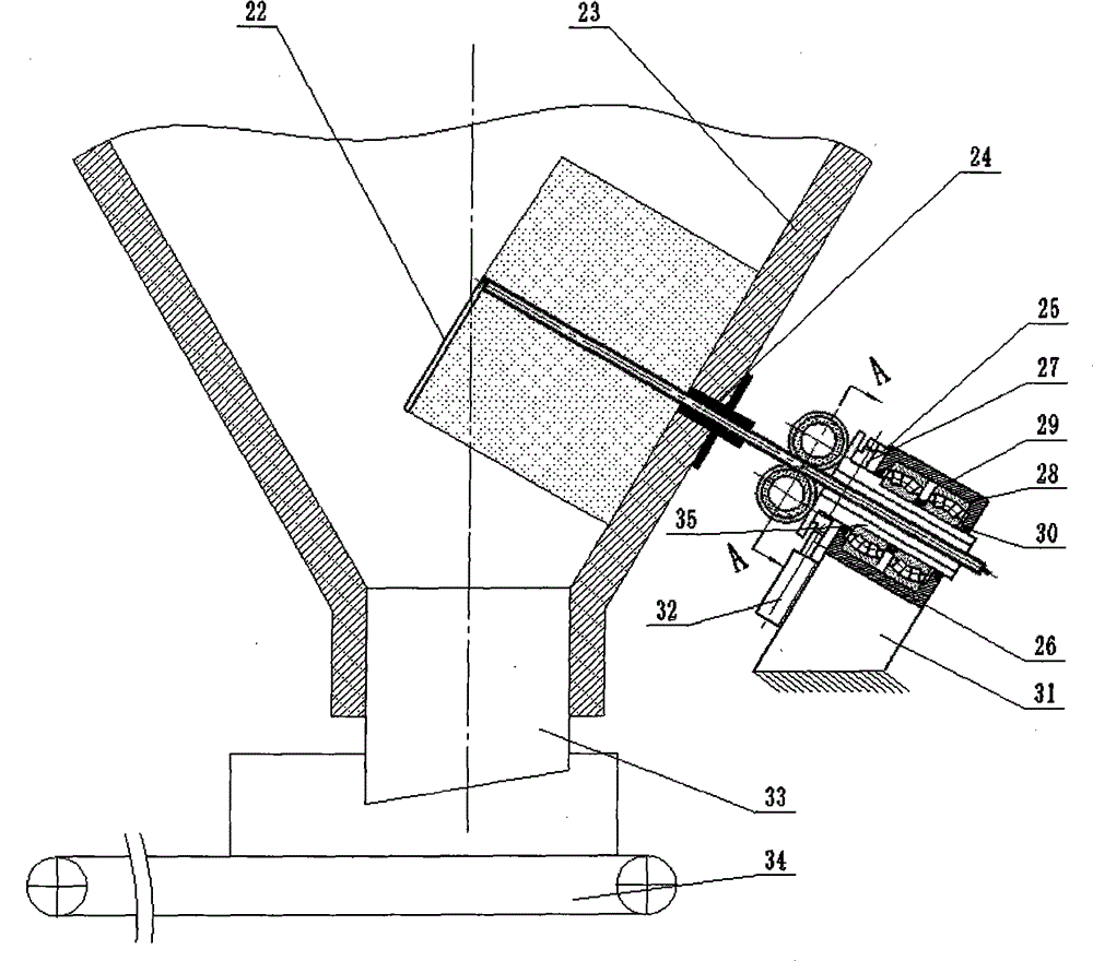
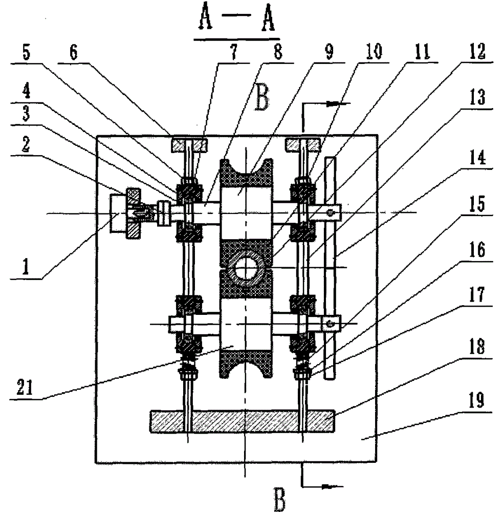
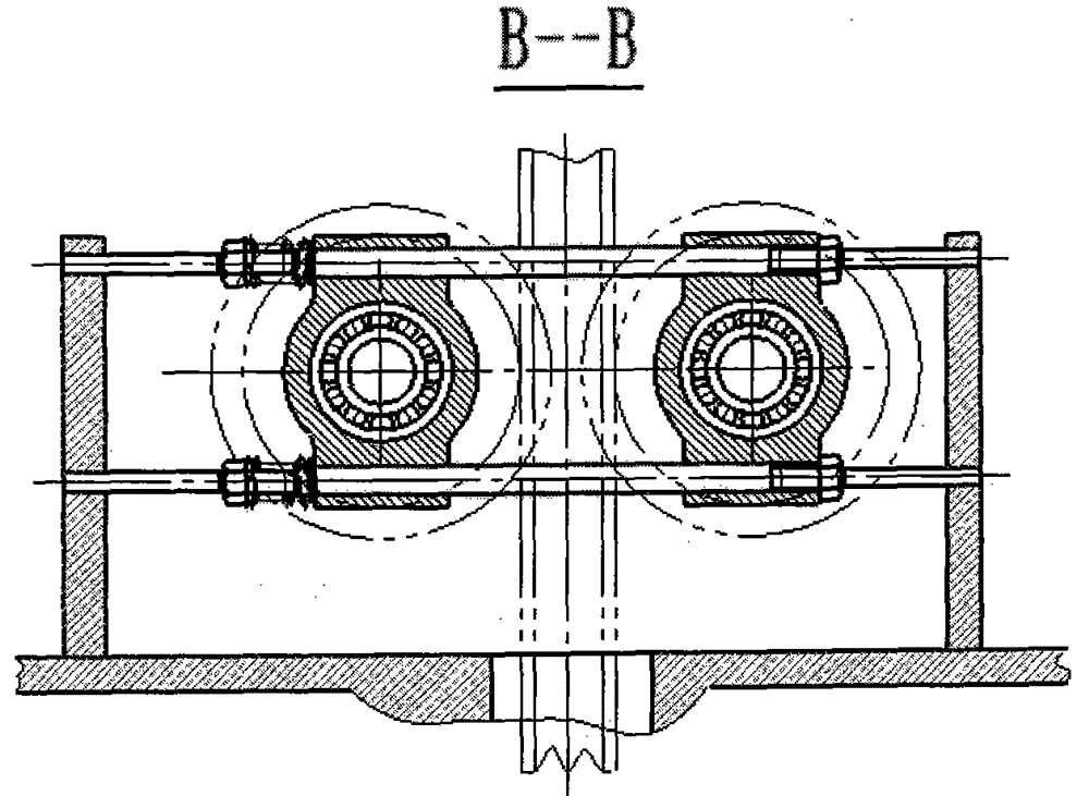
[0035] Embodiment one: see figure 1 , figure 2 , image 3, the guide sleeve 24 is installed on the silo wall of the silo 23, and the distance-adding rod 22 is hinged at the end of the arch-breaking rod 12. One end of the arch-breaking rod is installed in the guide sleeve, and the other end is clamped in the clamp Between the holding wheel 9 and the outer edge polymer elastic groove 11 of the afterburner clamping wheel 21, the left and right connecting plates 6, 18 are connected on the wheel seat 19, and the two ends of the circular guide post 13 are connected and fastened on the left and right connecting plates , the shaft seat 10 is installed in series on the circular guide post, and is driven to rotate by the rotary drive device 1 through the wheel shaft 8 and the coupling 2 . The two clamping wheels are installed on the shaft seats at both ends through the wheel shaft and the bearing 7, and the shaft seats of the stressed clamping wheels are positioned on the circular gu...

Embodiment 2

[0037] Embodiment two: see Figure 4 , The difference between this embodiment and Embodiment 1 is that the clamping force cylinder 20 is used to drive the shaft seat to move on the circular guide post so that the clamping wheel can generate clamping force on the broken arch bar. The clamping force of this structure is easy to adjust, and the adjustment range is large, and the clamping force can be released at any time by releasing the pressure of the oil cylinder.

Embodiment 3

[0038] Embodiment three: see Figure 5 , Figure 6 , in this embodiment, the wheel seat 10 is directly installed on the inner hinge seat 39 of the spherical hinge, and the outer hinge seat 38 matched with the inner hinge seat is installed on the silo wall through the connecting anchor rod 36, and the inner hinge seat A central hole is provided on the hole, and a guide ring 42 is installed in the hole, and the broken arch rod passes through the guide ring and enters in the feed bin. The other end of the broken arch rod is equipped with a swing ring 43 which is equivalent to a hinge sleeve and has an inner diameter greater than the outer diameter of the broken arch rod. The swing ring is connected with two swing cylinders 41 distributed at an angle of 90°, and the swing cylinder is hinged on the foundation and supported by the oil cylinder backing plate 40, an annular flexible gasket 37 is connected between the inner gallows and the outer hinge seat to adapt to the swing of the...


PUM


Abstract

The invention relates to auxiliary equipment for prompting falling of materials in a stock bin, in particular to a stock bin arch-breaking device for eliminating arching of materials in the stock bin, and belongs to the field of material conveying. In modern industrial production, a large quantity of stock bins are needed for storing materials. Due to various reasons, the materials are arched in the stock bins and cannot be discharged out of the stock bins normally, and normal implementation of the functions of the stock bins is severely influenced. The stock bin arch-breaking device comprises a stock bin, an arch-breaking rod, a clamping wheel train and a support, wherein the clamping wheel train at least comprises two opposite clamping wheels; the outer edges of the clamping wheels are of groove structures; the arch-breaking rod is a hollow pipe, is clamped between grooves of the clamping wheels, and is inserted into the stock bin. The arch-breaking rod is clamped by the clamping wheels, and the clamping wheels rotate to drive the arch-breaking rod to enter the stock bin through a through hole formed in the bin wall of the stock bin for performing arch breaking; the stock bin arch-breaking device has the advantages of simple and practical structure, elimination of limitations on the arch-breaking distance, adoption of a plurality of combined arch breaking ways for arch breaking, and the like.

Description

technical field [0001] The invention relates to an auxiliary device for promoting the falling of materials in a silo, in particular to a silo arch breaking device for eliminating arching of materials in the silo, belonging to the field of material transportation. Background technique [0002] Modern industrial production requires a large number of silos to store materials. Due to various reasons, the materials have arching phenomenon in the silos, which makes the materials unable to be sent out of the silos normally, seriously affecting the normal function of the silos. In order to solve these problems, people have taken various technological measures and invented various technological equipment, such as manual poking, air cannon, explosive blasting, mechanical vibration, hydraulic mechanical poking, etc., but these technological measures and technological equipment all exist in this way. Such a problem cannot completely solve the problem of arching of materials in the exist...

Claims


Application Information

Patent Timeline
Patent Type & Authority Applications(China)
IPC IPC(8): B65D88/70
CPCB65D88/703
Inventor 吴振卿
Owner ZHENGZHOU UNIV
Why Eureka
Try Eureka