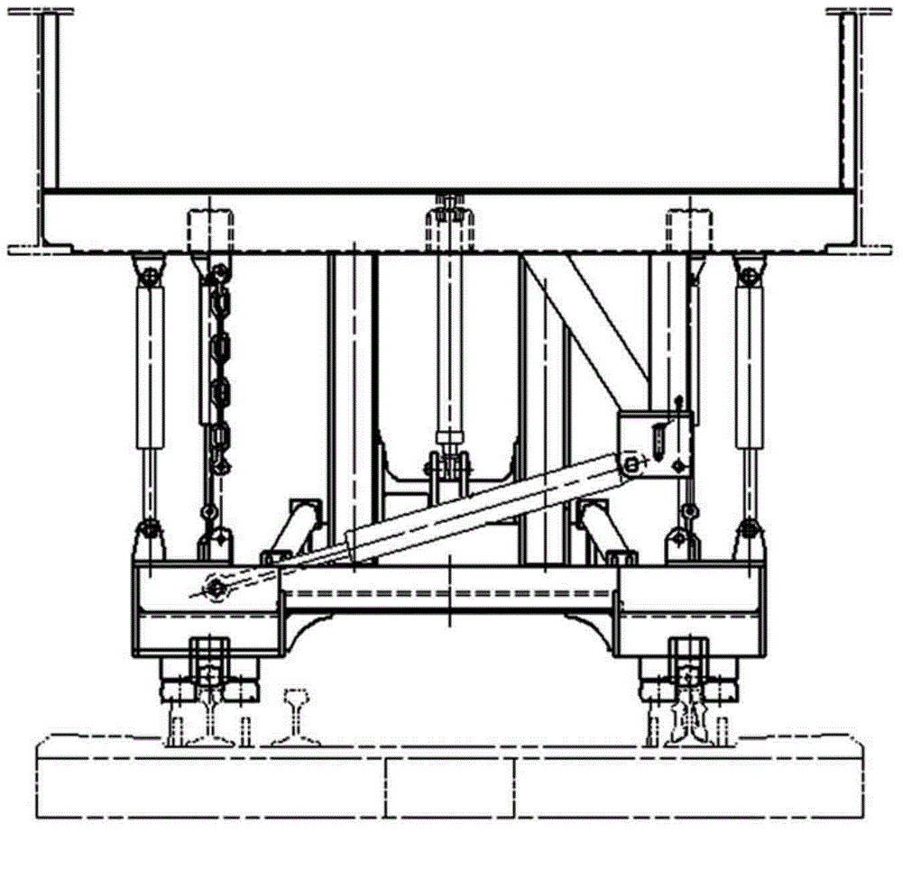
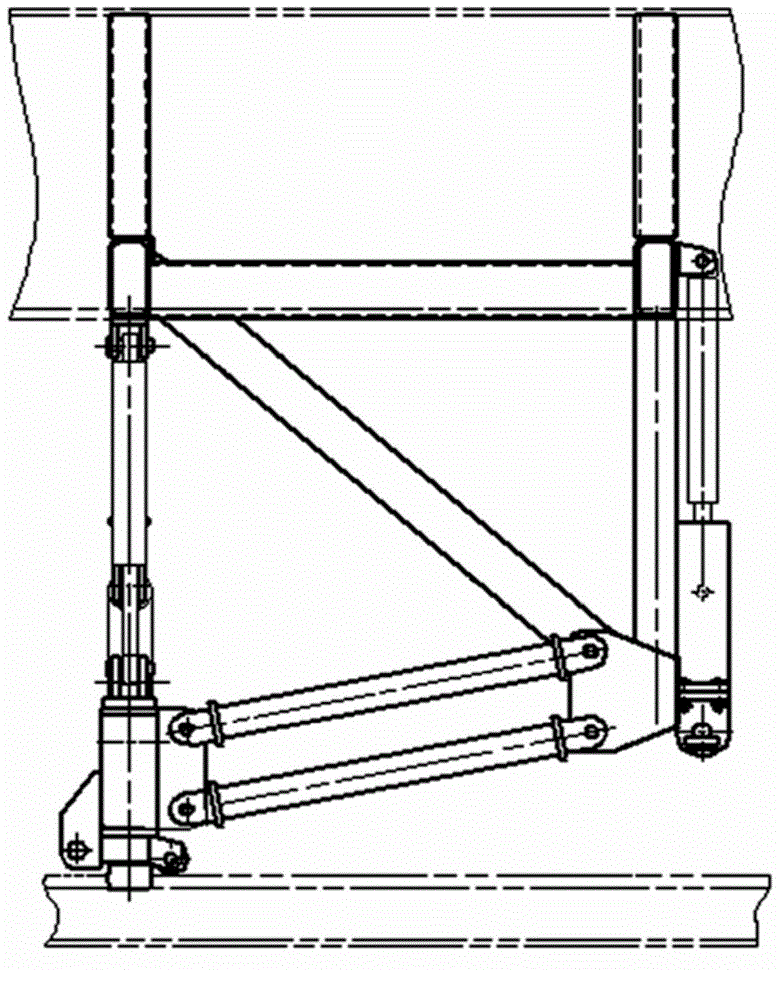
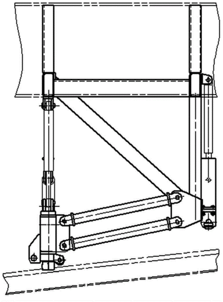
[0048] For the sake of reference and clarity, the technical terms, abbreviations or abbreviations used below are recorded as follows:
[0049] Longitudinal: along the direction of travel of the vehicle;
[0050] Horizontal: in the plane of the rail, the direction perpendicular to the longitudinal direction;
[0051] Vertical: The direction perpendicular to the rail plane of the rail.
[0052] In order to make the purpose, technical solutions and advantages of the embodiments of the present invention more clear, the technical solutions in the embodiments of the present invention will be clearly and completely described below in conjunction with the drawings in the embodiments of the present invention. Apparently, the described embodiments are only some of the embodiments of the present invention, not all of them. Based on the embodiments of the present invention, all other embodiments obtained by persons of ordinary skill in the art without creative efforts fall within the protection scope of the present invention.
[0053] as attached Image 6 to attach Figure 23 As shown, specific embodiments of the rail retractable device of the present invention are provided, and the present invention will be further described below in conjunction with the accompanying drawings and specific embodiments.
[0054] as attached Image 6 , 7 , 8, 9 and 10, a specific embodiment of a rail retractable device, the rail clamping device is installed under the car body chassis of the railway track changing vehicle, including: a positioning assembly, and a rail clamp fixed thereon support components. The positioning assembly further includes a strip-shaped guide seat 3 provided with guide rails along the length direction at the bottom, a hanger component 1 extending vertically from the underframe of the vehicle body, and two vertically extending from the underframe of the vehicle body. The retractable vertical oil cylinder 2 extending vertically downward, and the guide seat 3 can move vertically under the promotion of the vertical oil cylinder 2 . The guide seat 3 is a box structure formed by welding an upper cover plate, a lower cover plate, a web plate and a rib plate. The rail clamping assembly further includes sliders 4 arranged in pairs at the lower parts of both ends of the guide seat 3 , and the sliders 4 can move laterally along the length direction of the guide seat 3 . The interior of Slider 4 is further set up with:
[0055] The long clamping wheel 5 and the short clamping wheel 7 are arranged opposite to each other along the length direction of the guide seat 3, and the rail head of the rail 17 is movable;
[0056] It is located at the rear of the long clamping wheel 5 and the short clamping wheel 7, and is arranged opposite to each other along the length direction of the guide seat 3, and always maintains the rail head roller 12 for fixedly clamping the rail head of the rail 17, and the rail bottom roller adopts scroll wheel;
[0057] The upper part between the long pinch wheel 5 and the short pinch wheel 7 is arranged, and the rail top pinch wheel 6 that exerts downward pressure on the rail surface of the steel rail 17 is kept all the time.
[0058] The rail retracting device described in the above-mentioned specific embodiments of the present invention is applied to the railway rail changing operation, and the rail top pressure wheel 6, the movable clamp wheel and the rail head resting wheel 12 are embedded in the slide block 4, and the movable clamp wheel (long The combination of clamping wheel 5 and short clamping wheel 7) and rail head roller 12 controls the position of the rail 17, can clamp and move the rail according to the needs of changing rails, and effectively control the force of the rail so that it can enter the bearing smoothly. Rail grooves are suitable for the needs of railway track changing operations.
[0059] as attached Image 6 As shown, the positioning assembly further includes a horizontal adjustment cylinder 10 and a connecting rod 11. The fixed end of the horizontal adjustment cylinder 10 is connected to the side of the guide seat 3, and the movable end of the horizontal adjustment cylinder 10 is connected to the slide block 4, and is located on the guide seat 3. The two sliders 4 at the lower parts of both ends are fixedly connected by connecting rods 11 , and the combination of the two sliders 4 can move laterally along the length direction of the guide seat 3 under the push of the horizontal adjustment cylinder 10 . The bottom of guide seat 3 is equipped with two groups of rollers symmetrically, and every group of rollers is made up of two rail head leaning wheels 12 and a rail top pressing wheel 6, and slide bearing is installed in the rollers. The center-to-center distance of the two groups of rail top pressure rollers 6 is always kept at 1505mm, which is consistent with the fixed width between the two rails 17 . When the rail-changing vehicle performs the rail-changing operation on the curve, the horizontal adjustment oil cylinder 10 controls the slider 4 to slide along the guide seat 3 according to the offset detected between the rail clamping assembly and the rail 17 along with the variation of the offset.
[0060] as attached Figure 15 and 16 As shown, one end of the vertical oil cylinder 2 is connected to the hanger composition 1 or the car body chassis, and the other end is connected to the guide seat 3. The hanger composition 1 is provided with a vertically extending positioning plate 13, and the guide seat 3 can be positioned on the vertical oil cylinder. 2 and move vertically along the positioning plate 13 under the promotion of 2. As a typical specific embodiment of the present invention, the movable connection of the chute-rail structure is adopted between the positioning plate 13 and the guide seat 3 . The positioning plate 13 is provided with a chute 23 , the guide seat 3 is provided with a guide rail 22 , and the guide seat 3 can move vertically along the chute 23 of the positioning plate 13 under the promotion of the vertical oil cylinder 2 through the guide rail 22 . As another typical embodiment of the present invention, the movable connection of the guide post-guide sleeve structure is adopted between the positioning plate 13 and the guide seat 3 . The positioning plate 13 adopts a guide column structure, and the guide seat 3 is provided with a guide sleeve. The guide seat 3 can move vertically along the positioning plate 13 under the promotion of the vertical oil cylinder 2 through the guide sleeve. The vertical direction of the guide seat 3 in the space The position is controlled by vertical cylinder 2.
[0061] as attached Figure 8 As shown, the guide seat 3 is equipped with a pneumatic locking mechanism. When the rail retractable device is in a non-working state, the device is hung on the car body chassis by its own weight through the mechanism. The pneumatic locking mechanism further includes a mounting oil cylinder 16 , a fixing seat 21 and a hook 25 , and the fixing seat 21 is arranged on the hanger assembly 1 located on the upper part of the positioning plate 13 . The fixed end of the oil cylinder 16 is arranged on the guide seat 3, the hook 25 includes a first end, a second end and a third end, the first end of the hook 25 is connected with the movable end of the oil cylinder 16, the hook 25 The second end of the hook 25 links to each other with the positioning plate 13, and the third end of the hook 25 can be hung on the fixed seat 21 by the fixed hole on the fixed seat 21 when the rail retractable device is in the hanging state. When the rail retractable device is in working condition, loosen the connection between the third end of the hook 25 and the fixed seat 21, and the guide seat 3 can move vertically along the positioning plate 13 under the promotion of the vertical oil cylinder 2.
[0062] as attached Figure 11 and 12 As shown, the slider 4 further includes three longitudinal plates 15 disposed on the lower part of the guide seat 3 and extending down the longitudinal direction of the guide seat 3. The L-shaped longitudinal plates 15 are provided with reinforcing partitions. The bottom of the guide seat 3 is provided with a T-shaped guide rail 19, and the cover plate 24 at the top of the slider 4 is provided with a T-shaped chute 20, and the slider 4 can pass through the T-shaped chute 20 along the T-shaped guide rail 19 of the guide seat 3. move. The movement of the slider 4 is fixed on the side of the guide seat 3 by the fixed end, and the telescopic horizontal adjustment oil cylinder 10 connected with the slider 4 at the movable end is controlled, and the two sliders 4 are connected by a connecting rod 11 . When two groups of rail clamping components clamp the rail, the gauge of the rail 17 is 1505mm.
[0063] as attached Figure 13 , 14 , 20, 21, 22 and 23, the long clamping wheel 5, the rail top pressing wheel 6 and the short clamping wheel 7 are further arranged between two L-shaped longitudinal plates 15. A rail clamping oil cylinder is arranged between each movable clamping wheel and the slide block 4, and the pressure of the clamping rail oil cylinder is controlled within a certain range, and the clamping rail oil cylinder can control the swinging of the movable clamping wheel. One end of long clamping wheel 5 is hinged with slide block 4 by bearing pin 14, and the other end of long clamping wheel 5 is connected with the movable end of clamp rail oil cylinder two 9. One end of the short clamping wheel 7 is hinged with the slide block 4 by the bearing pin 14, and the other end of the short clamping wheel 7 is connected with the movable end of the clamping rail oil cylinder-8. The rail head roller 12 is arranged between the two L-shaped longitudinal plates 15 at the rear of the long clamp wheel 5 and the short clamp wheel 7 . The rail retracting device described in the specific embodiment of the present invention differs in the clamping mode of the rail 17 in that: the present invention performs swing control through the long clamping wheel 5 and the short clamping wheel 7, and the two sliders 4 are connected in a single horizontal oil cylinder through the connecting rod 11. Slide together under the effect of 10, and the center of two groups of slide blocks 4 is fixed. Because the present invention clamps the rails 17 in different ways, when the slide block 4 in the present invention passes through the connecting splint 18 between the rails 17, the long clamping wheel 5 and the short clamping wheel 7 will be pushed away temporarily. Now, the rail head of steel rail 17 is controlled by the rail head leaning wheel 12 that position is fixed, passes through connecting splint 18 smoothly, and two movable clamp wheels get back to original position afterwards. When carrying out the operation of changing rails, the rail crest pressure wheel 6 applies a downward pressure to the rail crest of steel rail 17 under the effect of vertical oil cylinder 10 all the time. The rail head roller 12 clamps the rail head of the rail 17 all the time under the effect of the clamping rail oil cylinder. When connecting splint 18 passed roller, connecting splint 18 can strut movable clamp wheel, and after connecting splint 18, movable clamp wheel clamps the rail head of rail 17.
[0064] as attached Figure 17 , 18As shown in and 19, when two groups of clamping rail assemblies clamp the rail 17, the distance between the centers of the two groups of rail top pressure rollers 6 remains consistent with the fixed width between the two rails 17. The rail head rollers 12 and the rail top pressure rollers 6 are cylindrical rollers, and the relative positions between the four rail head rollers 12 are fixed. The rail head is clamped. as attached Figure 19 As shown, when the rail retractable device passes through the connecting splint 18 between the rails 17, the first rail clamping cylinder 8 is extended, and the second rail clamping cylinder 9 is shortened, and the space between the long clamping wheel 5 and the short clamping wheel 7 increases , so that the rail retractable device passes through the connecting splint 18 smoothly. Now, the rail head leaning wheel 12 that is positioned at the long clip wheel 5 and the short clip wheel 7 rear parts still clamps the rail head of the rail 17, keeps the position of the rail 17. as attached Figure 18 As shown, when the rail retractable device passes through the connecting splint 18, the long clamping wheel 5 and the short clamping wheel 7 are respectively reset under the action of the rail clamping oil cylinder one 8 and the rail clamping oil cylinder two 9, and keep the rail head of the rail 17 clamping. In a specific embodiment of the present invention, since the long clamping wheel 5 and the short clamping wheel 7 can be made long enough, the gauge of the rail 17 can be better controlled when not passing through the connecting clamp 18, and when passing through the connecting clamp 18 It can be automatically stretched, thereby avoiding the connecting splint 18. The rail crest roller 6 is located between two L-shaped longitudinal plates 15 of the slider 4, and in the longitudinal direction, the distance between the long pinch wheel 5, the short pinch wheel 7, and the rail head roller 12 is very short, so Upturning or sagging of the rail 17 will not cause the rail 17 to disengage from the rail clamping mechanism. The rail retracting device described in the specific embodiment of the present invention is used for the new rail to be placed into the rail support groove and then enters the rear bogie. Functionally, the new rail can be controlled at a time of 1435mm (the inner margin of the rail) The rail 17 can be controlled at a certain height under the action of the rail top pressure, so as to avoid the bolts of the rail bearing groove and prevent the interference between the rail and the bolts on the operation curve. At the same time, the distance between the rail clamping assembly and the rail 17 can be automatically adjusted so that the rail 17 can smoothly enter the rail bearing groove.
[0065] By implementing the rail retracting device described in the specific embodiments of the present invention, the following technical effects can be achieved:
[0066] (1) In the rail retractable device described in the specific embodiment of the present invention, the rail head resting wheel, movable clamping wheel (long clamping wheel, short clamping wheel) and rail top pressing wheel are all built in the inside of the slider, and the structure is compact, Reduces the possibility of the rail breaking away from the rail clamping device due to upturning or sagging;
[0067] (2) The rail retractable device described in the specific embodiment of the present invention controls the position of the rail through the combination of movable clamp wheels (long clamp wheels, short clamp wheels) and rail head rollers, which increases the length of the clamp wheels, and then increases the The effective range of clamping the rail can prevent the rail from detaching from the clamping device when passing through the connecting splint of the rail, and always maintain the gauge before the rail enters the rail bearing groove.
[0068] Each embodiment in this specification is described in a progressive manner, each embodiment focuses on the difference from other embodiments, and the same and similar parts of each embodiment can be referred to each other.
[0069] The above descriptions are only preferred embodiments of the present invention, and do not limit the present invention in any form. Although the present invention has been disclosed above with preferred embodiments, it is not intended to limit the present invention. Any person familiar with the art, without departing from the spirit and technical solutions of the present invention, can use the methods and technical content disclosed above to make many possible changes and modifications to the technical solutions of the present invention, or modify them to be equivalent Variations of equivalent embodiments. Therefore, any simple modifications, equivalent replacements, equivalent changes and modifications made to the above embodiments according to the technical essence of the present invention, which do not deviate from the technical solutions of the present invention, still fall within the protection scope of the technical solutions of the present invention.