Turbo propeller

A propulsion device and turbine technology, which is applied to thrust reversers, pump devices, components of pumping devices for elastic fluids, etc. The effect of high compression ratio

Inactive Publication Date: 2015-04-29
王晓军
View PDF0 Cites 6 Cited by
  • Summary
  • Abstract
  • Description
  • Claims
  • Application Information

AI Technical Summary

Problems solved by technology

[0002] A locomotive running in a vacuum pipe, since there is no air resistance, the speed of the locomotive may be increased to thousands of kilometers per hour under the same energy consumption, but the construction of such a huge vacuum pipe is quite complicated and expensive

Method used


Image

  • Turbo propeller
  • Turbo propeller

Examples


Embodiment Construction

[0013] specific implementation

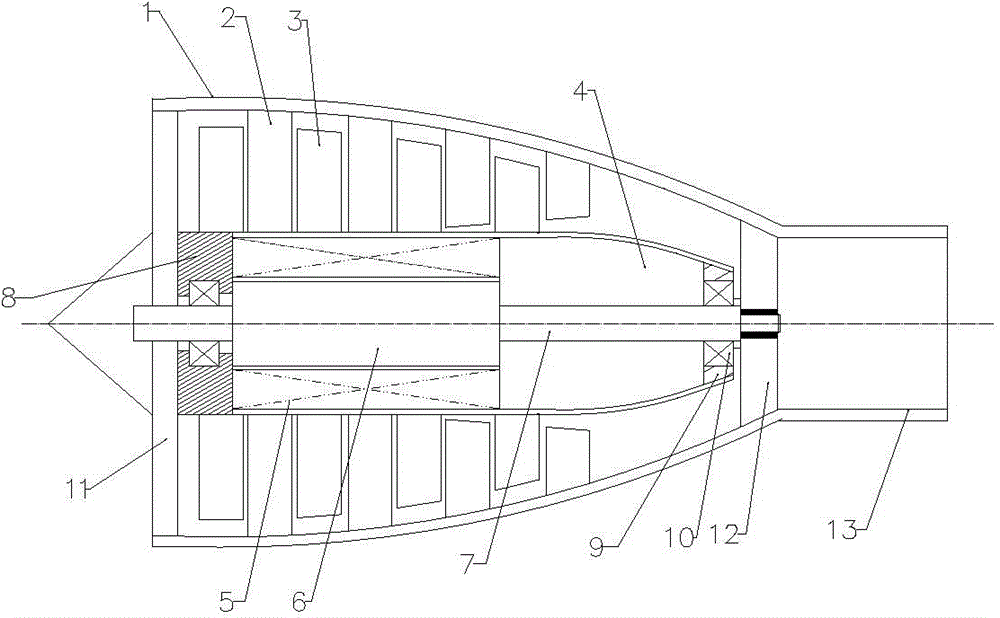
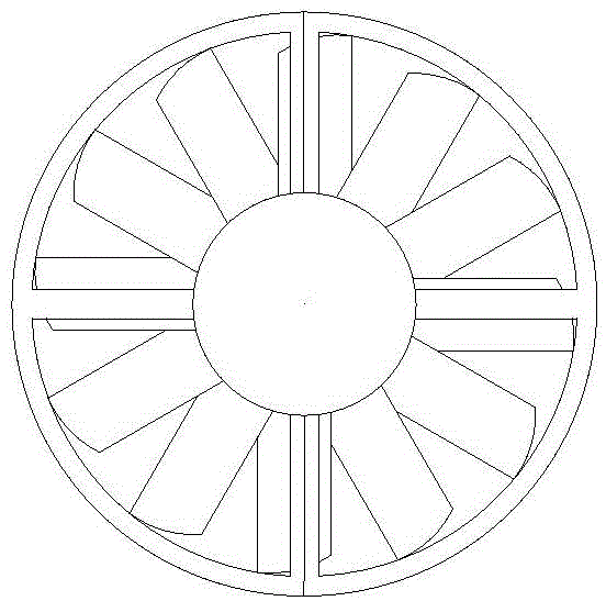
[0014] Such as figure 1 , 2 Shown: a turbine propulsion device, including a casing (1), a multi-stage stator grid (2) fixed on the inner wall of the casing (1), and a multi-stage grid alternately distributed between two static blades. The turbofan (3), the semi-conical hollow sleeve (4) for fixing the multi-stage turbofan (3), the electric motor set in the semi-conical hollow sleeve (4), the front and rear bearings supporting the semi-conical hollow sleeve (4) Plates (8), (9) fix the air inlet grille (11) and the air outlet grille (12) of the output shaft (7) at both ends of the motor, and the jet pipe connected to the air outlet grille (12) (13);

[0015] It is characterized in that: the shell (1) is conical, which is composed of two halves of the shell; the length direction of the grid surface of the multi-stage vane grid (2) is Curved surface, cascades with the same length are divided into two groups, starting from the air inlet of the h...


PUM


Abstract

The invention provides a turbo propeller applicable to driving a rail locomotive. A motor drives a turbo compressor to compress the air entering the turbo compressor; the compressed air is ejected by an ejector tube to generate recoil force; the recoil force drives the rail locomotive to move; the air in front of the rail locomotive moving can be sucked and compressed from the rear so as to increase the rear pressure of the rail locomotive, the air pressure of the front of the rail locomotive drops, and a severalfold pressure difference is generated to drive the rail locomotive to move.

Description

technical field [0001] The invention relates to a turbine propulsion device, which is suitable for driving power of rail locomotives. Background technique [0002] The locomotive running in the vacuum pipe, because there is no air resistance, the speed of the locomotive may be increased to thousands of kilometers per hour with the same energy consumption, but the construction of such a huge vacuum pipe is quite complicated and expensive. Contents of the invention [0003] The invention provides a turbine propulsion device, which uses a motor to drive a turbine compressor, compresses the air entering the compressor, and sprays it out through a jet tube to generate a recoil force; as the driving power of a rail locomotive, it can move the locomotive forward The air in the front of the locomotive is sucked in and pressed out from the rear to increase the pressure at the rear of the locomotive, while the air pressure at the front of the locomotive drops, thus generating severa...

Claims


Application Information

Patent Timeline
Patent Type & Authority Applications(China)
IPC IPC(8): F03H99/00F04D25/08F04D29/54F04D29/52F04D29/32
CPCF03H99/00F04D19/022F04D25/0613F04D25/08F04D29/322F04D29/522F04D29/542
Inventor 王晓军
Owner 王晓军
Why Eureka
Try Eureka