release device for clutch

A separation device and clutch technology, applied in clutches, fluid-driven clutches, non-mechanical-driven clutches, etc., can solve the problems of high cost and welding process consumption.

Active Publication Date: 2020-10-27
SCHAEFFLER TECH AG & CO KG
View PDF3 Cites 0 Cited by
  • Summary
  • Abstract
  • Description
  • Claims
  • Application Information

AI Technical Summary

Problems solved by technology

The welding process is relatively intensive and expensive

Method used


Image

  • release device for clutch
  • release device for clutch
  • release device for clutch

Examples


Embodiment Construction

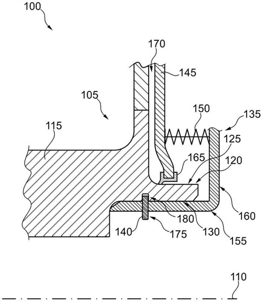
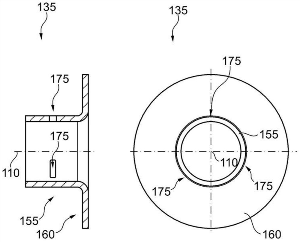
[0023] figure 1 A schematic side view of a part of clutch 100 with hydraulic release device 105 is shown. Both clutch 100 and hydraulic release device 105 are mounted rotatably about a rotational axis 110 . The separating device 105 comprises a rotatable component 115 , which can be designed in particular as a shaft stud or hub, with a hollow cylindrical end section 120 . In the region of the end section 120 there is a radially outer surface 125 and a radially inner surface 130 . In addition, the hydraulic separation device 105 includes a support element 135 , a safety element 140 , a hydraulic piston 145 and an elastic element 150 . The support element 135 comprises an axial section 155 and a radial section 160 , the radial outer side of which lies against the end section. On the radially inner surface 130 of 120 , the radial section extends in the radial direction beyond the end section 120 . The spring element 150 is arranged between the piston 145 and a radial section ...


PUM


Abstract

The invention discloses a separating device for a clutch. The separating device comprises a transmission member, a hydraulic piston, a supporting member, and an elastic member. The transmission member has an end segment having a column-shaped cavity; the hydraulic piston can move axially on the surface relative to the end portion segment and is used for defining a hydraulic working cavity; the supporting member is installed on the member which is capable of rotating; the elastic member is used for providing the axial expanding force supporting between the component and the piston in order to reduce the hydraulic working cavity. As a result, the supporting member comprises a radial segment which is axially adhered on the elastic member and a axial segment which is adhered on the end portion of the component which is capable of rotating. The supporting is retained at the component which is capable of rotating along the axial direction by depending on a safety component.

Description

technical field [0001] The invention relates to a disconnecting device for a clutch. In particular, the invention relates to a hydraulic release device for a clutch, for example in a powertrain of a motor vehicle. Background technique [0002] Clutches in the motor vehicle drivetrain have the task of forwarding or decoupling the torque provided, in particular by the drive motor, to a downstream component, such as the transmission. To this end, the clutch can be actuated with different strengths. In one specific embodiment, the greater the degree of actuation, the clutch is always engaged progressively more strongly, for which purpose the first friction disk connected to the clutch input side is pressed axially against the second friction disk connected to the clutch output side. on the friction plate. [0003] In a hydraulically actuated clutch, a hydraulic working chamber can be provided which is closed on an axial side by a piston which acts axially on one of the fricti...

Claims


Application Information

Patent Timeline
Patent Type & Authority Patents(China)
IPC IPC(8): F16D25/06F16D25/12
CPCF16D25/06F16D25/12
Inventor J·芬克J·阿诺尔德
Owner SCHAEFFLER TECH AG & CO KG
Why Eureka
Try Eureka