Separating device for clutch
A separation device, clutch technology, applied in clutches, fluid-driven clutches, non-mechanical-driven clutches, etc., can solve problems such as high cost and welding process consumption
- Summary
- Abstract
- Description
- Claims
- Application Information
AI Technical Summary
Problems solved by technology
Method used
Image
Examples
Embodiment Construction
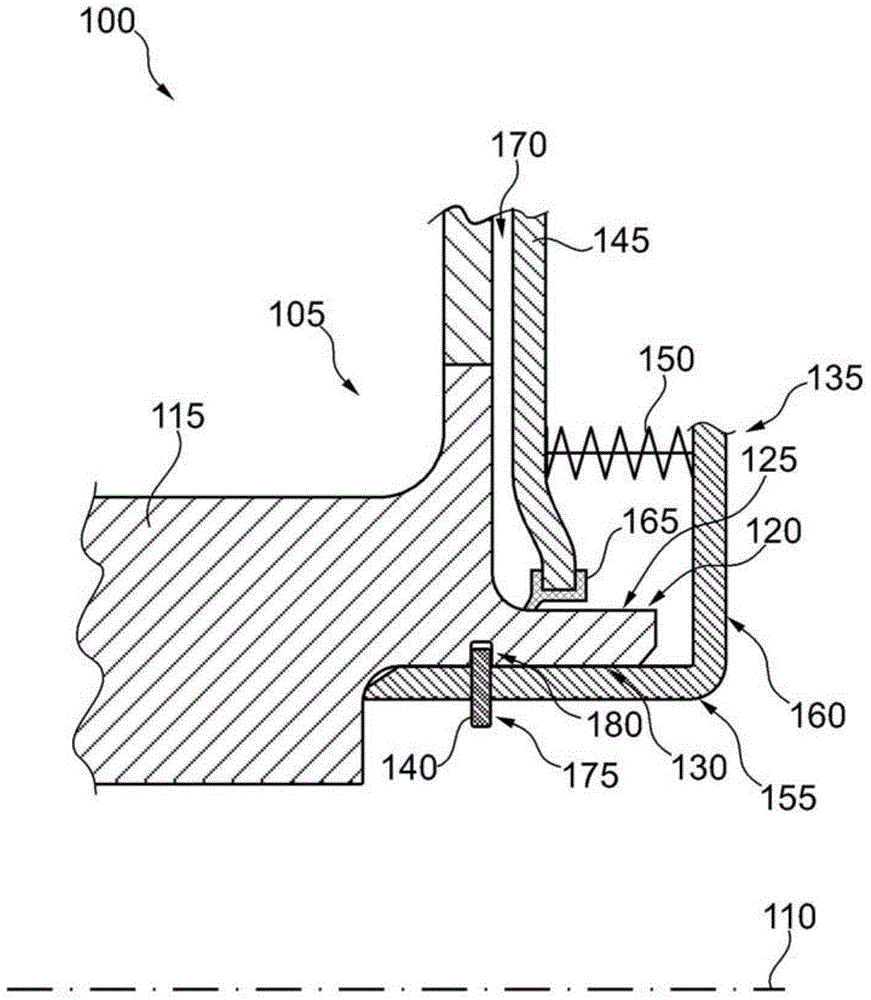
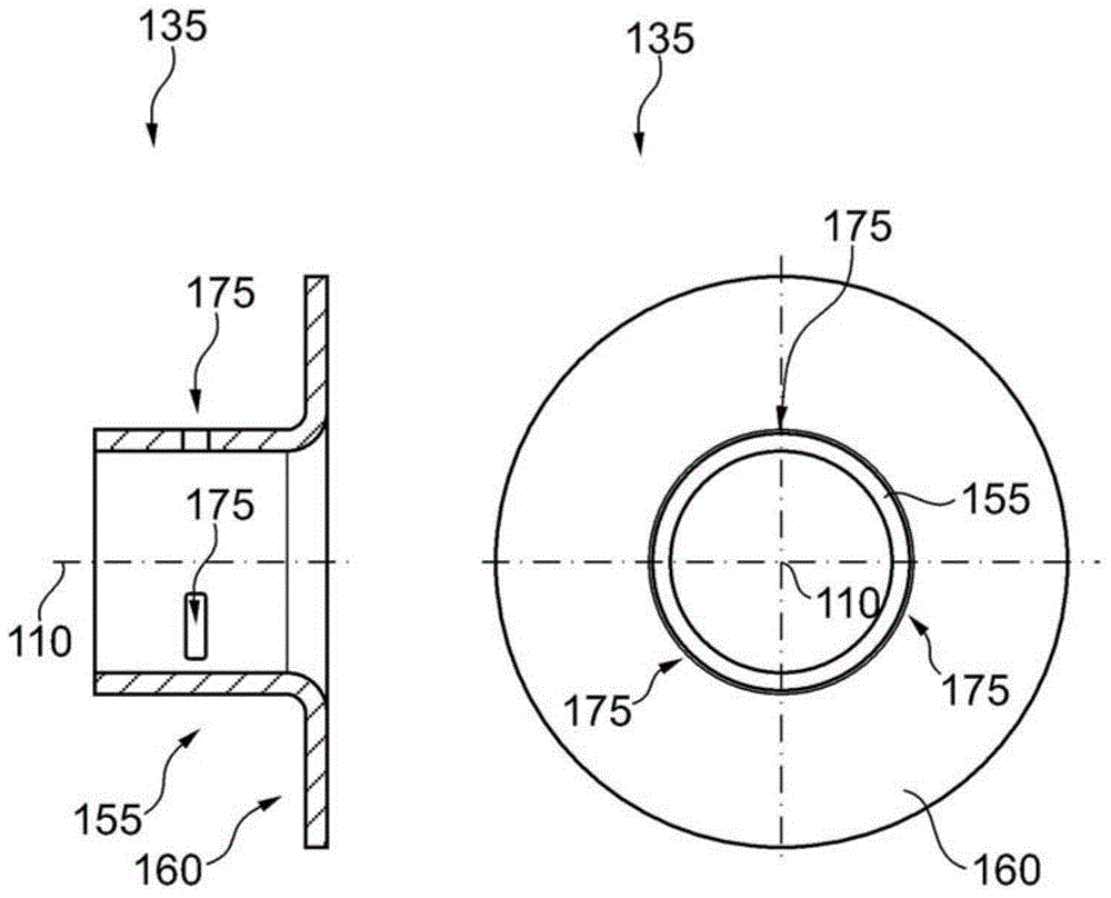
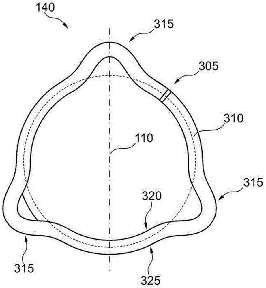
[0023] figure 1 A schematic side view of a part of clutch 100 with hydraulic release device 105 is shown. Both clutch 100 and hydraulic release device 105 are mounted rotatably about a rotational axis 110 . The separating device 105 comprises a rotatable component 115 , which can be designed in particular as a shaft stud or hub, with a hollow cylindrical end section 120 . In the region of the end section 120 there is a radially outer surface 125 and a radially inner surface 130 . In addition, the hydraulic separation device 105 includes a support element 135 , a safety element 140 , a hydraulic piston 145 and an elastic element 150 . The support element 135 comprises an axial section 155 and a radial section 160 , the radial outer side of which lies against the end section. On the radially inner surface 130 of 120 , the radial section extends in the radial direction beyond the end section 120 . The spring element 150 is arranged between the piston 145 and a radial section ...
PUM
 Abstract
Description
Claims
Application Information
 - R&D
- Intellectual Property
- Life Sciences
- Materials
- Tech Scout
- Unparalleled Data Quality
- Higher Quality Content
- 60% Fewer Hallucinations
Browse by: Latest US Patents, China's latest patents, Technical Efficacy Thesaurus, Application Domain, Technology Topic, Popular Technical Reports.
© 2025 PatSnap. All rights reserved.Legal|Privacy policy|Modern Slavery Act Transparency Statement|Sitemap|About US| Contact US: help@patsnap.com


