Lubrication and cooling system for gear case

A lubricating cooling and gear box technology, applied in the direction of gear lubrication/cooling, belt/chain/gear, transmission parts, etc., can solve the problems of difficulty in starting, inability to adapt, and waste of energy, saving energy and solving cooling problems. Insufficient use of area, effects of ensuring safety and availability

Active Publication Date: 2015-04-29
DALIAN SHINERGY SCI & TECH DEV
View PDF6 Cites 7 Cited by
  • Summary
  • Abstract
  • Description
  • Claims
  • Application Information

AI Technical Summary

Problems solved by technology

[0002] In the field of wind power, the existing gearbox lubrication and cooling systems mostly use fixed-speed cooler fans to cool down the cooler, and cannot adapt the wind speed to the temperature of different environments; these cooler systems also mostly use fixed high power oil pump motor, the torque of the oil pump motor of this cooling system is fixed, the oil pump motor with the same and fixed torque is used in low temperature and high temperature conditions, if the oil pump motor torque is large, the oil pump can be started under low temperature conditions, After the motor starts, the actual required torque is smaller than that at the start. Since the torque is fixed, the oil pump motor will still use this torque when it is running, which will inevitably cause energy waste. If the torque of the oil pump motor is small, not only is it difficult to start in low temperature conditions, but Starting under low temperature conditions may cause damage to the motor. Therefore, this cooling system generally needs to replace the fan motor and oil pump motor under different working conditions to adaptively adjust the fan speed and oil pump torque.

Method used


Image

  • Lubrication and cooling system for gear case
  • Lubrication and cooling system for gear case
  • Lubrication and cooling system for gear case

Examples


Embodiment

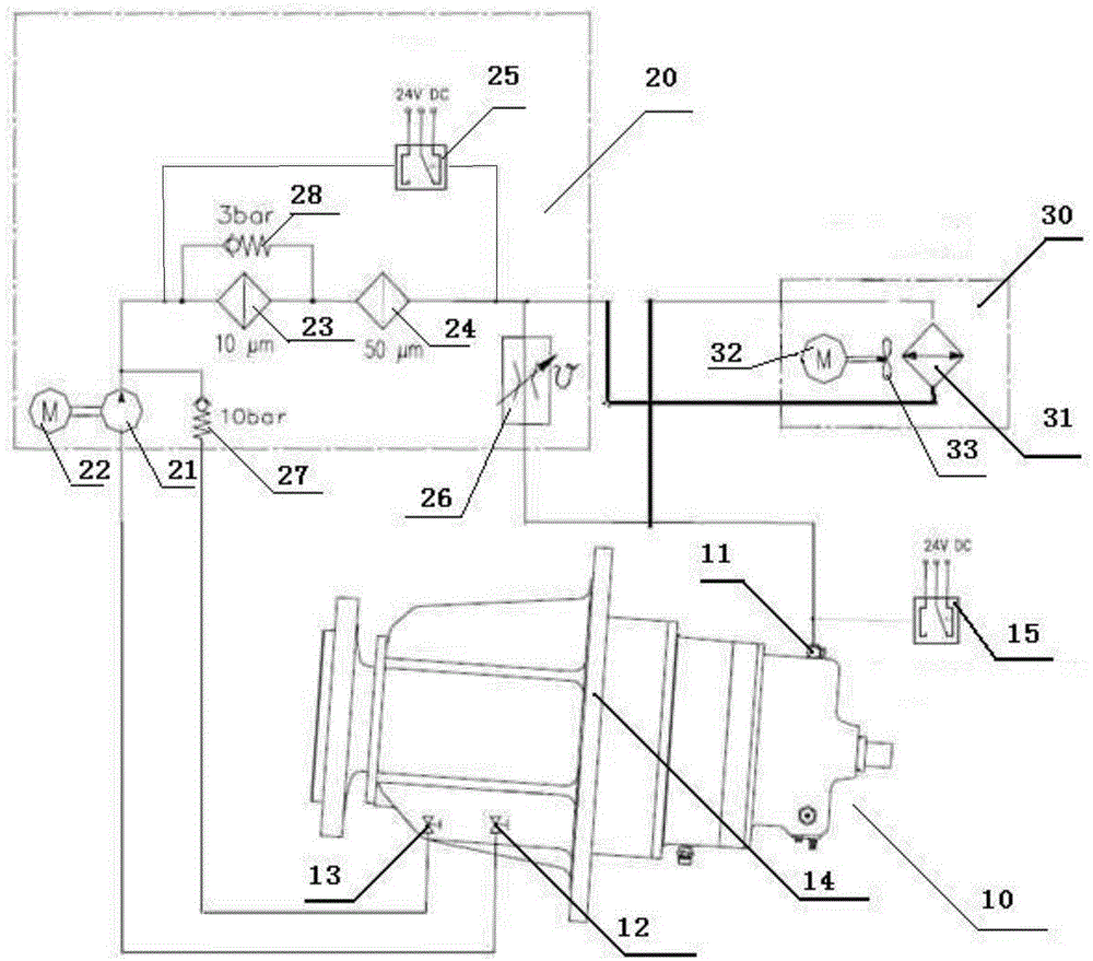
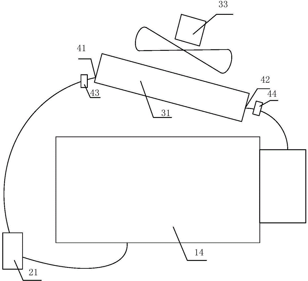
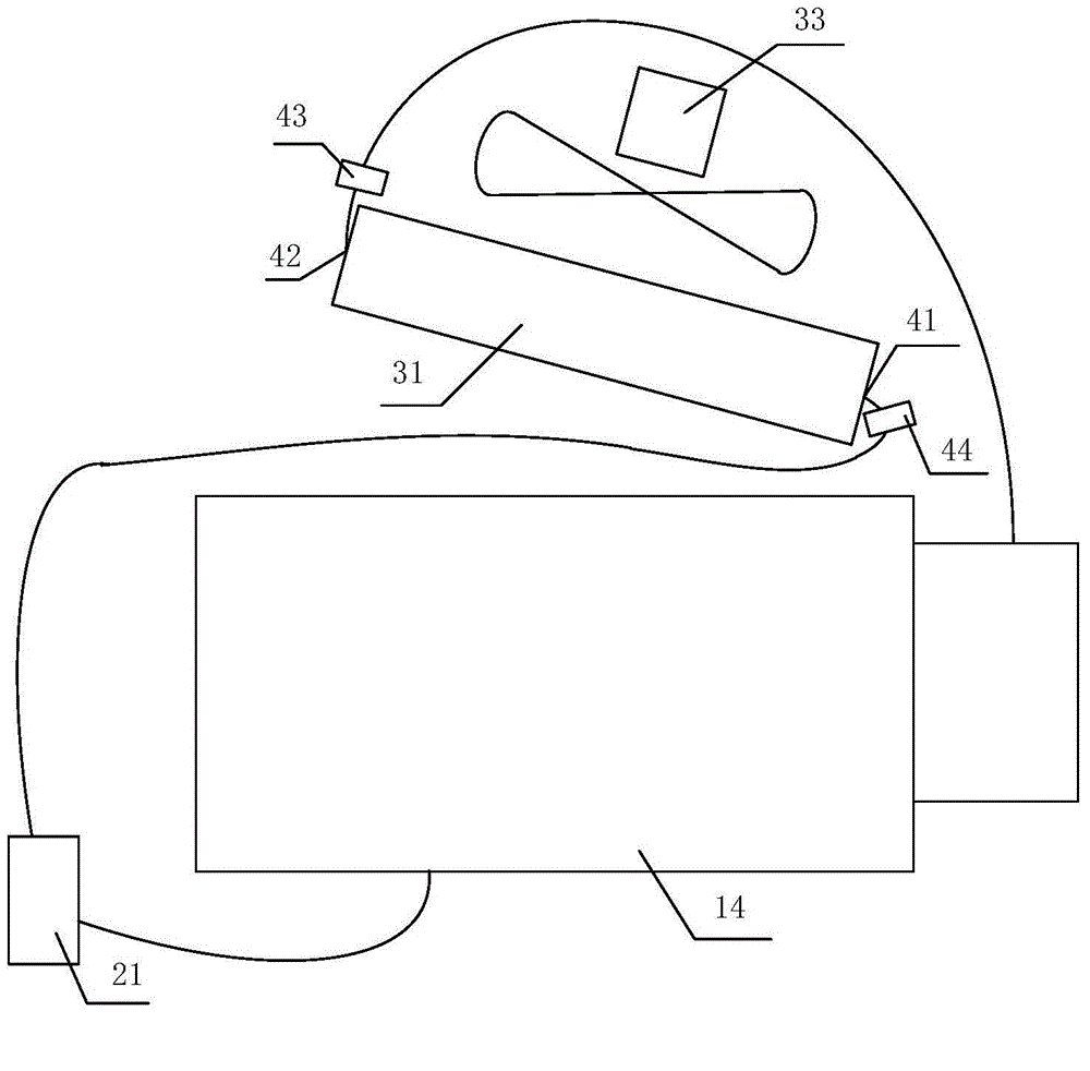
[0021] Example: such as Figure 1-3 As shown, a gearbox lubrication cooling system is composed of a gearbox unit 10, an oil pump unit 20 and a cooler unit 30, the gearbox unit 10 includes a gearbox 14, the oil pump unit 20 includes an oil pump 21, an oil pump motor 22, and the cooler unit 30 includes a cooler fan 33, a fan motor 32 and a cooler 31, the oil inlet of the oil pump 21 is connected to the oil outlet 12 of the gear box 14, the safety oil return port 13 of the gear box 14 is connected to the oil outlet of the oil pump 14, A one-way valve 27 is installed on the connecting pipe, and the oil pump motor 22 and the fan motor 32 are respectively connected with frequency converters. The frequency converter controls the speed of the oil pump motor 22 and fan motor 32. A temperature sensor for detecting the temperature of the gearbox oil tank is installed in the oil tank of the gearbox. The gear box 14 of this system is installed horizontally, the cooler 31 is installed dire...


PUM


Abstract

The invention discloses a lubrication and cooling system for a gear case. The lubrication and cooling system comprises an oil pump, an oil pump motor, a cooler fan, a fan motor and a cooler; the oil inlet of the oil pump is connected with the oil outlet of the gear case; the oil pump motor and the fan motor are respectively connected with a frequency changer; speed control is performed on the oil pump motor and the fan motor by the frequency changer; the control mode of the frequency changer is a PID (proportion integration differentiation) control mode; a temperature used for detecting the temperature of an oil groove of the gear case is arranged in the oil groove of the gear case. According to the lubrication and cooling system disclosed by the invention, on the basis of temperature information fed back by the temperature sensor arranged in the oil groove of the gear case, PID automatic control is performed on the running frequency of the oil pump motor and the running frequency of the fan motor, so that the control of the running speed of the fan and the running torque of the oil pump motor is realized by the frequency changer; in the start-up process and the running process of the oil pump motor, according to the conditions of the temperature and the viscosity of lubricating oil, the oil pump motor is smoothly started, and the goal that the energy is saved under the high temperature condition is achieved.

Description

technical field [0001] The invention relates to a cooling system, in particular to a system for lubricating and cooling a gearbox in a wind turbine. Background technique [0002] In the field of wind power, the existing gearbox lubrication and cooling systems mostly use fixed-speed cooler fans to cool down the cooler, and cannot adapt the wind speed to the temperature of different environments; these cooler systems also mostly use fixed high power oil pump motor, the torque of the oil pump motor of this cooling system is fixed, the oil pump motor with the same and fixed torque is used in low temperature and high temperature conditions, if the oil pump motor torque is large, the oil pump can be started under low temperature conditions, After the motor starts, the actual required torque is smaller than that at the start. Since the torque is fixed, the oil pump motor will still use this torque when it is running, which will inevitably cause energy waste. If the torque of the oi...

Claims


Application Information

Patent Timeline
Patent Type & Authority Applications(China)
IPC IPC(8): F16H57/04
CPCF16H57/0413
Inventor 马丁·费舍尔马静
Owner DALIAN SHINERGY SCI & TECH DEV
Why Eureka
Try Eureka