

Cooling and dedusting method of gearbox lubricating and cooling system
A technology for lubricating and cooling gear boxes, applied in gear lubrication/cooling, belts/chains/gears, transmission parts, etc. It can solve problems such as difficult blowing off of dust, difficulty in cleaning the oil film of cooler fans and coolers, etc., and achieves Solve the effect of insufficient utilization of cooling area and energy saving
- Summary
- Abstract
- Description
- Claims
- Application Information
AI Technical Summary
Problems solved by technology
Method used
Image

Examples
Embodiment Construction
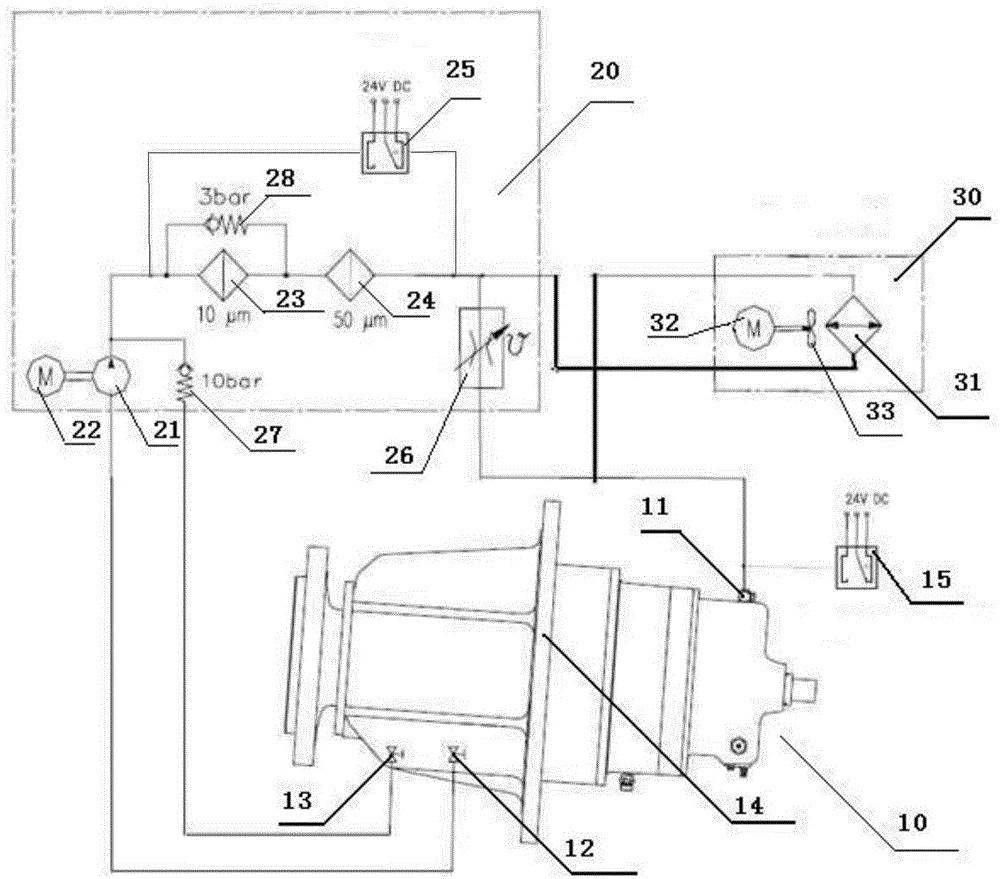
[0033] In order to illustrate the technical solution of the present invention more clearly, the present invention will be further described below in conjunction with the accompanying drawings and specific embodiments, as Figure 1-3 Shown:
[0034] A cooling and dust removal method for a gearbox lubricating cooling system, comprising the following steps:
[0035] S1. Assemble the gearbox lubrication and cooling system
[0036] S1.1. Connect the oil pump motor 22 and the fan motor 32 to the frequency converter respectively, and the frequency converter controls the speed of the oil pump motor 22 and the fan motor 32. The control mode is PID control, and the gear box 14 is installed in the oil tank for detection The temperature sensor of the gear box 14 oil tank temperature;
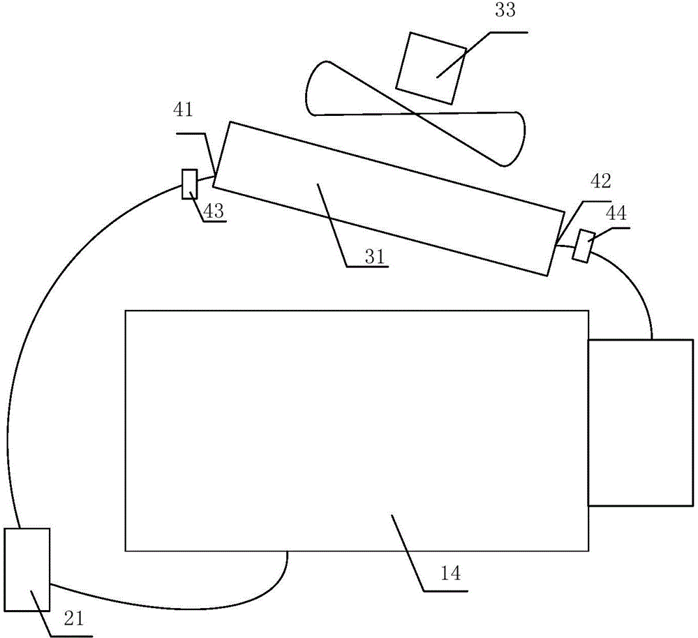
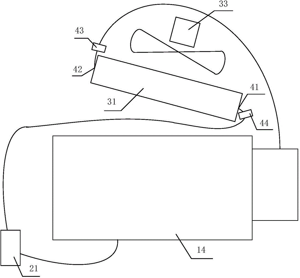
[0037] S1.2. The gear box 14 is installed horizontally. The cooler 31 is installed directly above the gear box 14 at an angle of inclination to the horizontal direction. The hot oil inlet 41 of the cooler...
PUM
 Abstract
Description
Claims
Application Information