Lens and light-emitting device

A lens and cylindrical lens technology, applied in the field of lenses and light-emitting devices, can solve the problems of the market expansion of direct-lit backlight modules, the high cost of backlight modules, and the incompatibility of LEDs with different structures, so as to eliminate hot spots. , Improve the uniformity of light and the effect of uniform light

Active Publication Date: 2015-04-29
THE HONG KONG POLYTECHNIC UNIV
View PDF4 Cites 12 Cited by
  • Summary
  • Abstract
  • Description
  • Claims
  • Application Information

AI Technical Summary

Problems solved by technology

In other words, at present, a lens can only be applied to LEDs of one structure, but not compatible with LEDs of different structures.
As a result, the cost of the lens and even the entire backlight module remains high, which has a serious impact on the market expansion of the entire direct-type backlight module

Method used


Image

  • Lens and light-emitting device
  • Lens and light-emitting device
  • Lens and light-emitting device

Examples


no. 1 approach

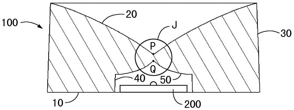
[0049] see figure 1 . The first embodiment of the lens of the present invention includes a lens body 100, and the lens body 100 has a bottom surface 10, a top surface and a peripheral surface. The middle part of the bottom surface 10 of the lens body 1 is concave inward to form a light incident surface, the top surface of the lens body 100 is a total reflection surface 20 , and the peripheral surface of the lens body 100 is a light output surface 30 .

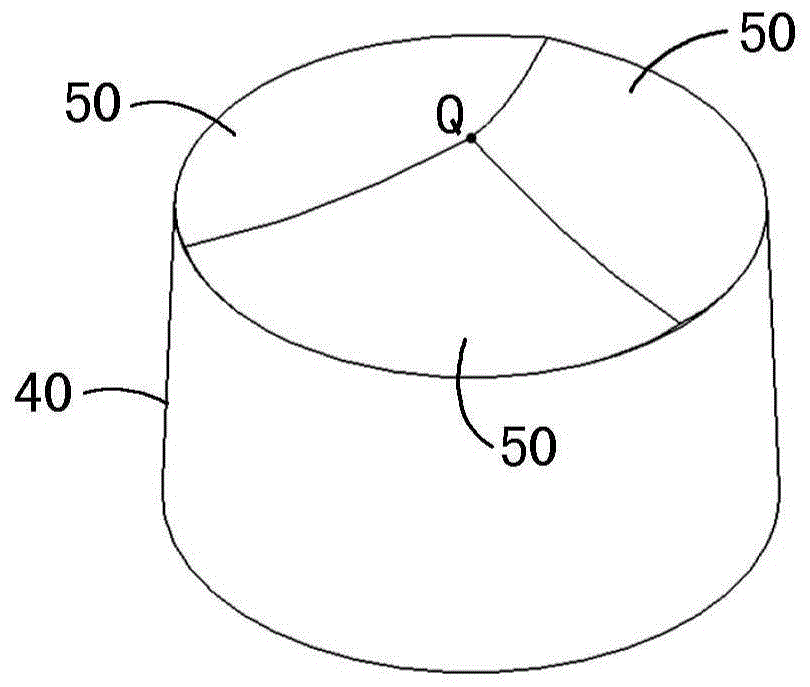
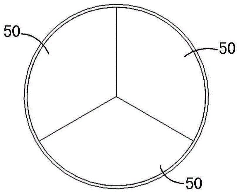
[0050] see figure 1 , Figure 2A to Figure 2D . The light incident surface includes a first light incident surface 40 and a second light incident surface 50 , wherein the first light incident surface 40 is cylindrical and its bottom end is connected to the bottom surface 10 of the lens 100 . The second light incident surface 50 is in the shape of a pyramid, and has a pyramid surface in the shape of a smooth transition surface and a pyramid apex Q. The bottom end of the second light incident surface 50 is connected to the t...

Embodiment approach 2

[0063] see Figure 6 and Figure 7 . The second embodiment of the lens of the present invention differs from the first embodiment only in that:

[0064] The second light incident surface 50 includes a second lower light incident surface 51 and a second upper light incident surface 52, and several upper outgoing light rays include several second outgoing light rays corresponding to the second lower light incident surface 51 and corresponding to the second light incident surface 52. Several third outgoing rays, several second outgoing rays and several third outgoing rays of the upper light incident surface 52 are arranged continuously. The height H3 of the second lower light incident surface 51 is 0.3 times of the height H4 of the second upper light incident surface 52, but not limited thereto, the height H3 of the second lower light incident surface 51 is the second upper light incident surface 52 The range of 0.2 to 0.5 times of the height H4 is feasible; the width W3 of th...


PUM


Abstract

The invention provides a lens and a light-emitting device. The lens comprises a column-shaped lens main body, wherein the column-shaped lens main body is provided with a bottom surface, a top surface and a circumference surface; the middle of the bottom surface concaves inwards to form a light incoming surface; the top surface is a total reflection surface in the shape of a smooth transitional curved surface and is provided with a center vertex; the circumference surface is a light extracting surface; the light incoming surface comprises a first cylindrical light incoming surface connected with the bottom surface and a second pyramid light incoming surface connected with the first light incoming surface; the second pyramid light incoming surface is provided with a pyramid vertex and pyramid surfaces in the shapes of smooth transitional curved surfaces; the center vertex of the total reflection surface and the pyramid vertex of the second light incoming surface are both on the axis of the lens main body; incident ray getting into the lens main body from the first light incoming surface is directly emitted out by the light extracting surface to form a plurality of first emergent rays upwardly inclined by 0-40 degrees relative to the bottom surface; incident ray getting into the lens main body from the second light incoming surface is reflected by the total reflection surface and then emitted out by the light extracting surface to form a plurality of top emergent rays which are upwardly or downwardly inclined. According to the invention, light leaking is effectively reduced.

Description

technical field [0001] The invention relates to a lens and a light-emitting device suitable for a backlight module, in particular to a lens and a light-emitting device suitable for an ultra-thin and large-size direct-type backlight module. Background technique [0002] In the direct-lit backlight module, the LED array is directly placed under the diffusion plate, and the light passes through the liquid crystal switch in a direct way. Since the direct-lit backlight module can use more groups of light sources, it can provide higher brightness and luminance, and is often used in large-size LCD TVs. Under the trend of large-scale LCD panels, direct-lit LED backlight modules have become the focus of market research and development at this stage. [0003] The challenges of using LEDs as direct-lit backlights mainly lie in the poor light uniformity and low luminous efficiency of traditional lenses, requiring a large light mixing distance and the existence of hot spots and other de...

Claims


Application Information

Patent Timeline
Patent Type & Authority Applications(China)
IPC IPC(8): F21S2/00F21V5/04
CPCF21K9/00F21V5/04
Inventor 杜雪王波张家儁王文奎
Owner THE HONG KONG POLYTECHNIC UNIV
Why Eureka
Try Eureka