Wavelength conversion device and light-emitting device

A technology of wavelength conversion device and wavelength conversion layer, which is applied in the field of light sources, can solve problems such as uneven intensity, uneven color, and unevenness of outgoing light

Inactive Publication Date: 2015-04-29
杨毅
View PDF5 Cites 18 Cited by
  • Summary
  • Abstract
  • Description
  • Claims
  • Application Information

AI Technical Summary

Problems solved by technology

However, the directivity of the laser is too strong, and the coherence is also strong, which causes unevenness of the outgoing light (including

Method used


Image

  • Wavelength conversion device and light-emitting device
  • Wavelength conversion device and light-emitting device
  • Wavelength conversion device and light-emitting device

Examples


Embodiment Construction

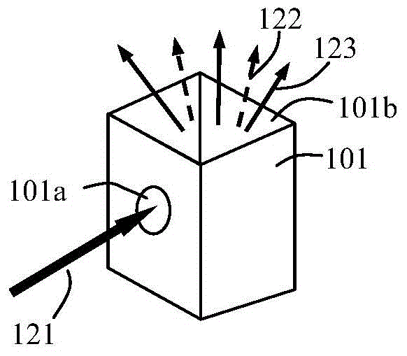
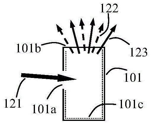
[0010] The present invention proposes a wavelength conversion device, the structural schematic diagram of the first embodiment is as follows Figure 1A As shown, its cross-sectional view is shown in Figure 1B shown. The wavelength conversion device includes a cavity 101, at least part of the inner surface of the cavity 101 is a reflective inner surface, and the reflective inner surface includes a wavelength conversion layer 101c. The cavity 101 includes a light entrance 101a and a light exit 101b. The light entrance 101a is used to receive the incident excitation light 121. After the excitation light is incident on the cavity, it will excite the wavelength conversion layer on its inner surface to emit the stimulated light. 123, the received light 123 finally exits from the light exit 101b. Wherein, the sum of the areas of the light entrance 101 a and the light exit 101 b is smaller than the area of ​​the remaining inner surface of the cavity 101 , and the positions of the li...


PUM

PropertyMeasurementUnit
The average thicknessaaaaaaaaaa

Abstract

The invention discloses a wavelength conversion device and a light-emitting device. The wavelength conversion device comprises a cavity, wherein at least partial inner surface of the cavity is a reflection inner surface, and a wavelength conversion layer is arranged on the reflection inner surface; the cavity comprises a light inlet and a light outlet, wherein the light inlet is used for receiving incident exciting light, the exciting light is incident to the cavity to excite the wavelength conversion layer on the reflection inner surface and enables the wavelength conversion layer to emit excited light, and the exited light finally is emergent from the light outlet; the sum of areas of the light inlet and the light outlet is smaller than area of the rest of the inner surface of the cavity; positions of the light inlet and the light outlet are not opposite. The wavelength conversion device is adopted, so that the exciting light and the excited light are emergent after being sufficiently reflected in the cavity; moreover, the exciting light cannot be directly project to the light outlet from the light inlet, so that the light-outlet uniformity of the light outlet is effectively guaranteed.

Description

technical field [0001] The invention relates to the field of light sources, in particular to a wavelength conversion device and a light emitting device using the wavelength conversion device. Background technique [0002] At present, the application of laser light source has been paid more and more attention. Laser has the advantages of high brightness and long life, but its spectrum is very narrow, so in use, laser is often used to excite fluorescent materials to form mixed luminescence. However, the directivity of the laser is too strong, and the coherence is also very strong, which causes unevenness of the outgoing light (including uneven intensity and uneven color). This problem has not been well resolved, which also restricts the prospect of laser light source for display. Contents of the invention [0003] The present invention proposes a wavelength conversion device, comprising a cavity, at least part of the inner surface of the cavity is a reflective inner su...

Claims


Application Information

Patent Timeline
IPC IPC(8): F21V9/10F21V7/00F21V9/40
CPCF21V7/00F21V9/40
Inventor 杨毅
Owner 杨毅
Why Eureka
Try Eureka