Redistribution device structure of heat exchanger

A redistributor and heat exchanger technology, applied in the direction of heat exchanger shell, heat exchange equipment, lighting and heating equipment, etc., to achieve the effect of expanding material selection, reducing pressure drop, and facilitating disassembly and installation

Active Publication Date: 2015-04-29
ZHENHAI PETROCHEM JIANAN ENG
View PDF6 Cites 1 Cited by
  • Summary
  • Abstract
  • Description
  • Claims
  • Application Information

AI Technical Summary

Problems solved by technology

[0004] The technical problem to be solved by the present invention is to provide a redistributor structure for heat exchangers with good gas-liquid two-phase mixing effect and easy assembly and disassembly in view of the current state of the art

Method used


Image

  • Redistribution device structure of heat exchanger
  • Redistribution device structure of heat exchanger

Examples


Embodiment Construction

[0017] The present invention will be further described in detail below in conjunction with the accompanying drawings and embodiments.

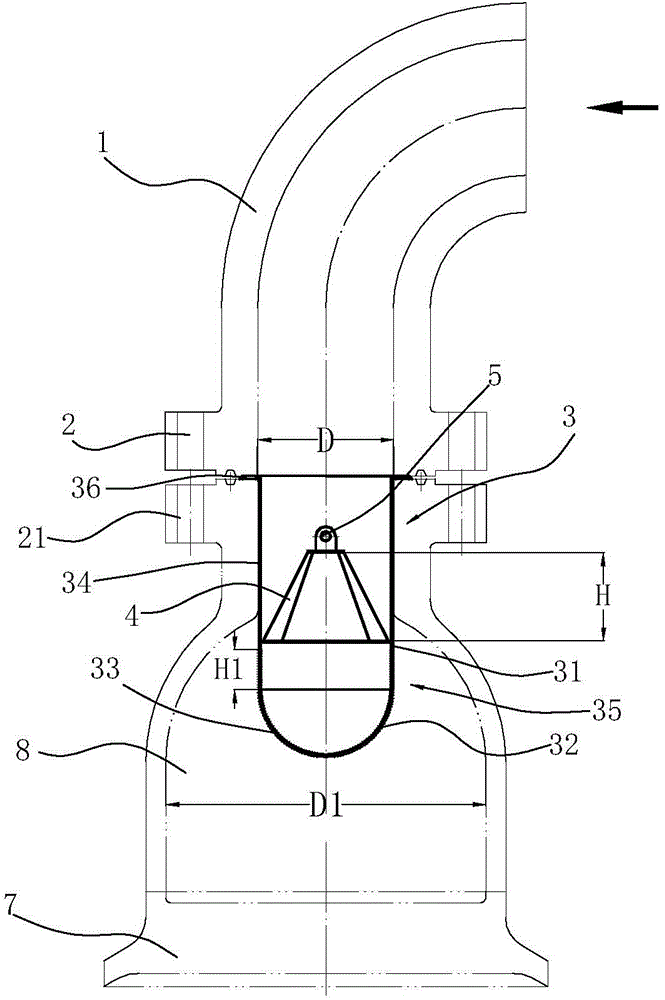
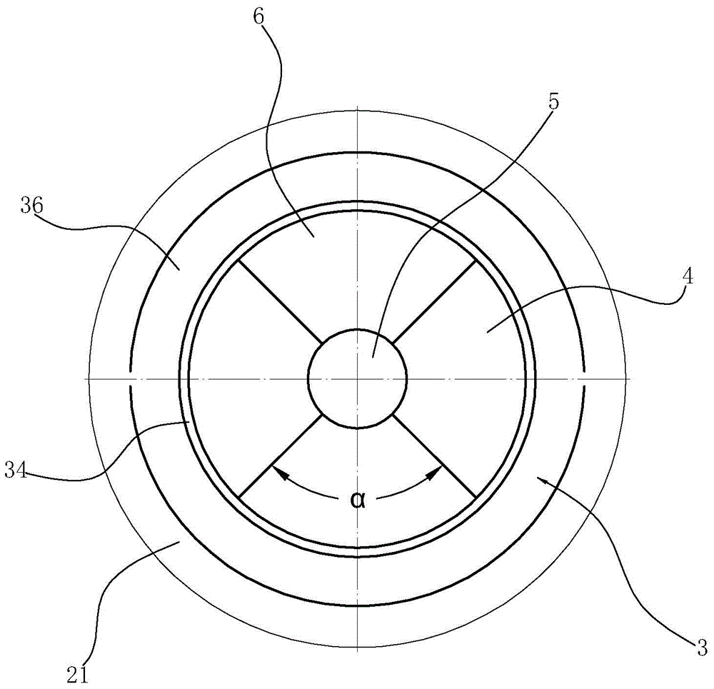
[0018] like figure 1 and figure 2 As shown, the redistributor structure for the heat exchanger is arranged in the tube box 8 of the heat exchanger, and the inlet flange 21 of the tube box 8 is detachably connected to the fluid delivery pipeline. The fluid delivery pipeline in this embodiment is connected to the pipe box through an elbow 1, and a connecting flange 2 connected to the inlet flange 1 is provided on the elbow 1. The inlet flange and the connecting flange in this embodiment are octagonal pads flange.

[0019] The redistributor 3 is arranged in the pipe box, and it includes a connecting sleeve 34 accommodated in the inlet flange 21, the lower end of the connecting sleeve 34 is connected with a redistribution bucket 35, and the upper end of the connecting sleeve 34 is connected with a The flange 36 is interposed between the inlet ...


PUM


Abstract

The invention relates to a redistribution device structure of a heat exchanger. The structure is characterized by comprising a redistribution device arranged in a channel of the heat exchanger; the redistribution device comprises a connection sleeve accommodated in an inlet flange of the channel, the lower end of the connection sleeve is connected to a redistribution barrel, and the outer side wall of the connection sleeve is provided with a convex edge connected to the inlet flange; a plurality of baffles are arranged in the connection sleeve, first ends of the baffles are connected to the upper end edge of the redistribution barrel, second ends of the baffles are connected, and gaps are formed between adjacent baffles; the redistribution barrel is located in the inner cavity of the channel, and the wall of the redistribution barrel is provided with a plurality of discharge holes communicated with the inner cavity of the channel. The welding procedure is avoided, the integrity and anti-corrosion properties of the inner wall of the channel can be guaranteed, and the heat process of the channel is facilitated; meanwhile, the redistribution device can be detached and installed conveniently, by means of the secondary flow mixing of the baffles and redistribution barrel, the gas-liquid phase mixing effect is better, and the pressure drop is reduced.

Description

technical field [0001] The invention relates to a redistributor structure, in particular to a redistributor structure for a heat exchanger. Background technique [0002] In the production process, it is usually necessary to exchange heat for the reaction materials. Some reaction materials are gas-liquid two-phase mixture materials. When the gas and liquid phases are mixed evenly, the heat exchange effect is good, and the pressure is reduced, and the equipment runs smoothly. [0003] In order to enable the gas-liquid two-phase mixed material to exchange heat evenly, the gas-liquid two-phase mixed material usually enters the redistributor before entering the heat exchanger, and the two phases are further mixed before being sent to the heat exchanger. In the prior art, a mixer is usually installed upstream of the heat exchanger, and the gas-liquid two-phase is mixed evenly through the mixer, so as to ensure the heat exchange effect. The existing mixer is generally an orifice p...

Claims


Application Information

Patent Timeline
Patent Type & Authority Applications(China)
IPC IPC(8): F28F9/22
Inventor 王健良张贤安胡兴苗刘利江李军杰
Owner ZHENHAI PETROCHEM JIANAN ENG
Why Eureka
Try Eureka