Tooling and test method for fiber optic gyroscope vibration test

A vibration test, fiber optic gyroscope technology, applied in vibration testing, measuring devices, testing of machine/structural components, etc., can solve the problems of uncertain placement of gyroscopes, inconvenient movement of tooling, insufficient screw tightening, etc., to reduce the number of connections. Unreliable factors, the effect of ensuring consistency and traceability, improving consistency and reliability

Active Publication Date: 2017-05-24
中航捷锐(西安)光电技术有限公司
View PDF9 Cites 0 Cited by
  • Summary
  • Abstract
  • Description
  • Claims
  • Application Information

AI Technical Summary

Problems solved by technology

This kind of tooling structure has several disadvantages: 1. There are many screws to be fastened, so the probability of insufficient screw tightening is relatively high; 2. The tooling is inconvenient to move, and it is not conducive to operation when changing the vibration direction of the gyro; 3. The placement of the gyro The location is relatively random, and the orientation of the gyro is uncertain, so it is not retroactive in subsequent data queries

Method used


Image

  • Tooling and test method for fiber optic gyroscope vibration test
  • Tooling and test method for fiber optic gyroscope vibration test
  • Tooling and test method for fiber optic gyroscope vibration test

Examples


Embodiment Construction

[0038] The scheme of the present invention will be described in detail below in conjunction with the accompanying drawings and embodiments. Among them, the accompanying drawings constitute a part of the application and are used to assist in explaining the technical solutions of the present invention.

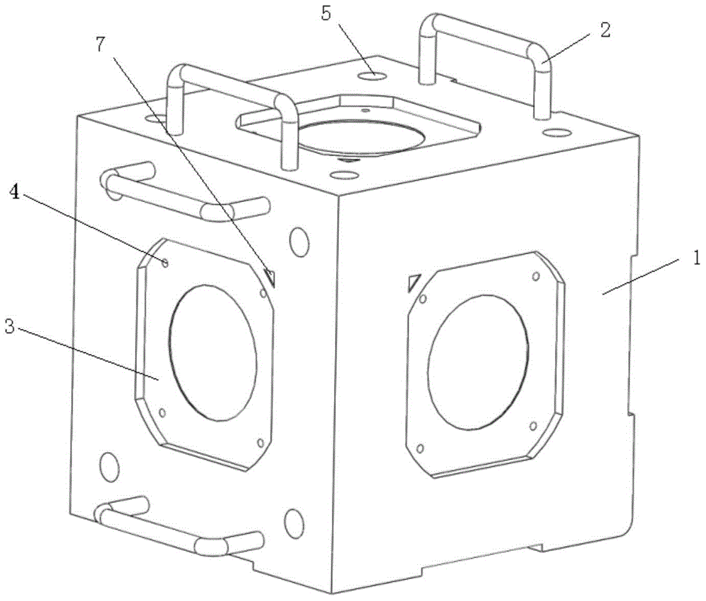
[0039] Aiming at the vibration test used in the environmental test of the interferometric fiber optic gyroscope, the present invention designs an effective vibration tooling and establishes scientific operating procedures, in order to minimize the impact of environmental vibration on the gyroscope accuracy, and at the same time improve the performance of the test test. work efficiency.

[0040] Vibration test tooling provided by the invention, such as figure 1 As shown, it includes a cube-shaped or cuboid-shaped tooling body 1, that is, a hexahedron whose two adjacent sides are perpendicular to each other. The tool body 1 has no electromagnetic shielding requirements, so alumi...


PUM


Abstract

The invention discloses a jig for a vibration test of a fiber-optic gyroscope and a testing method of the vibration test. The jig comprises a jig body, wherein two vertical planes of the jig are respectively provided with a handle; the side opposite to the handle is provided with a jig fixing substrate, and other sides are respectively provided with a gyroscope substrate and a gyroscope installation location mark; two adjacent vertical sides on the jig body are regarded as installation fixing sides, and other sides are provided with the gyroscope through the gyroscope substrate; during vibration test, the two installation fixing sides are respectively regarded as installation bases to be twice tested; after second round of test is executed, the jig rotates by 90 degrees in a horizontal plane along an anticlockwise or clockwise direction, and then third round of test is executed. The jig is specifically designed, so that the gyroscope can be fixed to the jig without using changeover measures, the installing position of the gyroscope on the jig is constant, the stability of the gyroscope is increased, the gyroscope can not loosen during vibration and the test accuracy is improved.

Description

technical field [0001] The invention belongs to the technical field of testing of fiber optic gyroscopes and fiber optic sensors, and in particular relates to a tooling used in vibration tests in fiber optic gyroscope environmental tests. Background technique [0002] At present, the medium and low-precision fiber optic gyro strapdown inertial measurement system has moved from the laboratory to the practical stage, but the application of the high-precision fiber optic gyro strapdown inertial measurement system is still limited by environmental conditions, especially vibration conditions. Theoretically speaking, compared with the mechanical gyroscope, the all-solid-state structure and no rotating moving parts of the fiber optic gyroscope determine that it has the advantages of shock resistance, vibration resistance, and high reliability. However, in practical applications, stress changes in fiber optic rings caused by shocks and vibrations, device pigtail vibrations, and stru...

Claims


Application Information

Patent Timeline
Patent Type & Authority Patents(China)
IPC IPC(8): G01C25/00G01M7/04
CPCG01C25/005G01M7/04
Inventor 霍雷梁利嘉魏珍妮赵鹏牛卫杰李学潮王已熏
Owner 中航捷锐(西安)光电技术有限公司
Why Eureka
Try Eureka