Stripline Resonator Fixture

A stripline and resonator technology, which is applied in the design and processing of stripline resonator fixtures, can solve the problems of uneven manufacturing precision and structure, and achieve the effect of reducing manufacturing requirements

Active Publication Date: 2017-11-14
JIANGNAN INST OF COMPUTING TECH
View PDF3 Cites 0 Cited by
  • Summary
  • Abstract
  • Description
  • Claims
  • Application Information

AI Technical Summary

Problems solved by technology

[0005] Since the main mode of stripline transmission is TEM mode, if the size is not selected properly, or the structure is uneven due to low manufacturing precision, high-order TE mode and TM mode will be generated.

Method used


Image

  • Stripline Resonator Fixture
  • Stripline Resonator Fixture
  • Stripline Resonator Fixture

Examples


Embodiment Construction

[0025] In order to make the content of the present invention clearer and easier to understand, the content of the present invention will be described in detail below in conjunction with specific embodiments and accompanying drawings.

[0026] In a preferred embodiment according to the present invention, the stripline resonator clamp comprises a lower clamping block part and an upper clamping block part which cooperate with each other.

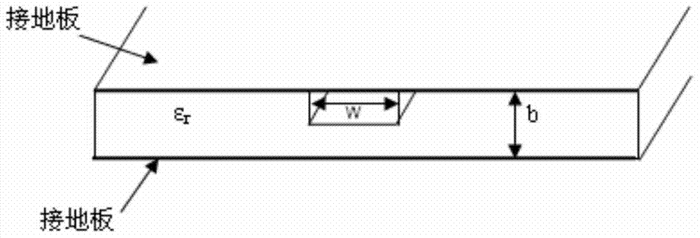
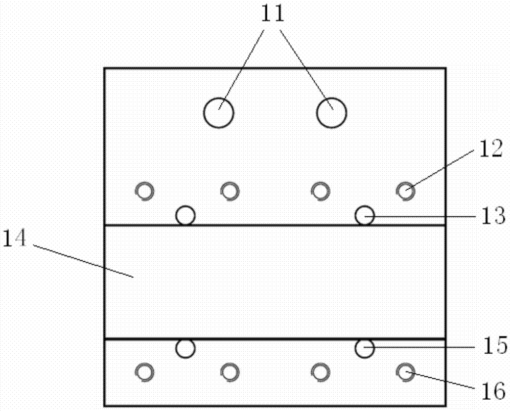
[0027] specifically, image 3 Schematically showing a top view of the lower clamping block part of the stripline resonator fixture used for the stripline method dielectric property test according to the preferred embodiment of the present invention, Figure 4 It schematically shows a cross-sectional view of the lower clamping block part of the stripline resonator fixture used for the dielectric property test of the stripline method according to the preferred embodiment of the present invention.

[0028] like image 3 and Figure 4 As shown, ...


PUM


Abstract

The present invention provides a stripline resonator metal clamp, comprising: an upper clamping block and a lower clamping block of the clamp; wherein, the lower clamping block includes: a positioning hole for fixing the lower clamping block on a workbench, It is used to arrange the groove of the medium substrate, the threaded hole for fixing the upper clamp block, and the positioning pin to prevent the upper clamp block and the medium substrate from sliding. Moreover, the upper clamping block includes: a positioning hole for fixing the upper clamping block, a groove for arranging the dielectric substrate, and a pin hole.

Description

technical field [0001] The invention relates to the field of dielectric performance testing of high-frequency dielectric materials, and more specifically, the invention relates to the design and processing of a stripline resonator fixture. Background technique [0002] With the high frequency of various communication systems and the high speed of network data systems, the application of high frequency dielectric materials in electronic products is becoming more and more extensive, and the demand for testing dielectric properties at GHz frequencies is also increasing. Among them, the stripline test method has the advantages of wide frequency band and easy operation, and has become a more commonly used test method at present. [0003] The stripline is to place a thin conduction strip with a width W in the middle between two wide conductor ground planes with a distance b, and the entire space between the two ground planes is filled with a dielectric with a dielectric parameter ...

Claims


Application Information

Patent Timeline
Patent Type & Authority Patents(China)
IPC IPC(8): G01R1/04
Inventor 张永华陈文录贾燕刘国平石小传邬宁彪李小明刘国立
Owner JIANGNAN INST OF COMPUTING TECH
Why Eureka
Try Eureka