Face detection apparatus and method

A face detection and face technology, applied in instruments, character and pattern recognition, computer parts, etc., can solve problems such as the reduction of the accuracy of the face model and the error convergence of the eye position of the model, so as to shorten the processing time, suppress the The effect of misfit

Active Publication Date: 2015-04-29
AISIN SEIKI KK
9 Cites 8 Cited by

AI-Extracted Technical Summary

Problems solved by technology

This situation is called misfitting, and when misfitting occurs, the accuracy of the face model decreases
In particular, it is...

Abstract

A face detection apparatus (1) detecting a face from an image which is captured by an imaging unit (2) and includes the face, includes: a position detection unit (11) that detects a position of a face part of the face from the image; an initial state determination unit (12) that determines a model initial state on the basis of the position of the face part; and a model fitting unit (13) that generates a model of the face on the basis of the image by using the model initial state.

Application Domain

Technology Topic

Computer visionModel fitting +5

Image

  • Face detection apparatus and method
  • Face detection apparatus and method
  • Face detection apparatus and method

Examples

  • Experimental program(1)

Example Embodiment

[0040] Hereinafter, an embodiment of the present invention will be described with reference to the drawings, but the present invention is not limited to this embodiment. In addition, in the drawings described below, structures having the same functions are denoted by the same reference numerals, and overlapping descriptions may be omitted.
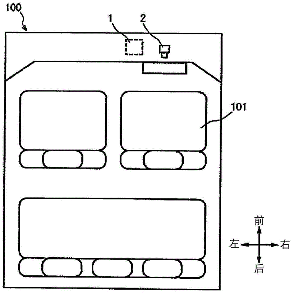
[0041] figure 1 It is a schematic diagram showing the compartment of the vehicle 100 equipped with the face detection device 1 according to the present embodiment. The vehicle 100 includes a face detection device 1 having an imaging unit 2. The face detection device 1 may be installed in any place in the vehicle 100. The face detection device 1 may be a stand-alone device, or it may be incorporated in another system (for example, a car navigation system) in the vehicle 100.
[0042] The imaging unit 2 is installed in the vehicle cabin in front of the driver's seat 101 (that is, on the traveling direction side of the vehicle 100). The imaging unit 2 is configured to be capable of imaging at least an area including the face of the driver sitting in the driver seat 101. In this embodiment, the imaging unit 2 is provided on the dashboard, but as long as the driver's face can be photographed from the front direction, it may be provided on the steering wheel, the ceiling, or the interior mirror.
[0043] figure 2 It is a schematic block diagram of the face detection device 1 according to the embodiment of the present invention. The face detection device 1 includes an imaging unit 2 for imaging the driver's face. The imaging unit 2 includes a camera 21 having a lens 23 and a control unit 22. The camera 21 may be a general CCD camera or MOS camera for visible light, and may also be an infrared camera. Compared with CCD cameras and MOS cameras for visible light, infrared cameras are not affected by individual skin colors. In addition, infrared cameras can make the shutter speed faster than visible CCD cameras and MOS cameras. In addition, the camera 21 may also be a JPEG camera module. The JPEG camera module is a module obtained by integrating the imaging unit and the A/D conversion unit. Compared with the visible light CCD camera and MOS camera, it is lighter and more compact. Therefore, when it is mounted on a vehicle, the mounting position In terms of superiority.
[0044] The control unit 22 controls the camera 21. The control unit 22 controls the lens 23 to automatically focus on the face of the driver sitting in the driver's seat 101, that is, controls the shutter of the camera 21 to open and close every predetermined time or in response to a signal from the CPU 8, and The captured image data is recorded as a frame in the frame memory 61 of the RAM 6. That is, an image captured at a certain time is called a frame.
[0045] In addition, the face detection device 1 includes a computing unit (CPU) 8, a storage unit 9, a ROM 5, a RAM 6, an output unit 7, an interface (I/F) 4, and a bus 41. In addition, when the camera 21 of the imaging unit 2 is not a JPEG camera, the face detection device 1 further includes an A/D (analog/digital) conversion unit 3. Each part is connected so as to be able to transmit and receive signals via the bus 41.
[0046] The arithmetic unit 8 includes a CPU, and has a function of processing and analyzing digitally converted image data from the imaging unit 2 according to a program, and performing processing such as eye detection and eye blinking determination. The storage unit 9 is composed of a RAM, a hard disk drive, and the like, and can store image data, and can store processing results, analysis results, and judgment results of the image data.
[0047] The output unit 7 includes, for example, a speaker, a display, and a lamp. The output unit 7 can emit a sound for reminding or warning from a speaker or output a message or light for reminding or warning from a display or a lamp based on the result of the face detection processing according to the present embodiment. In addition, the output unit 7 can also send a signal for operating the automatic brake to, for example, the automatic brake system of the vehicle 2 based on the result of the face detection processing according to the present embodiment.
[0048] As the speaker included in the output unit 7, a speaker equipped in the vehicle 2 can also be used. In addition, as a display included in the output unit 7, a display of a car navigation system equipped in the vehicle 2 can also be used.
[0049] The A/D conversion unit 3 has a function of converting the image signal from the imaging unit 2 into image data of a digital signal. The image data is output to the interface (I/F) 4. The I/F 4 exchanges data and commands with the control unit 22 and receives image data. ROM5 is a dedicated memory for reading, storing a boot program for starting up the face detection device 1, and is equipped with programs for storing executed processing, analysis, and judgment (for example, performing the following Image 6 , 7 , 9) the program memory 51. The program may not be stored in the ROM 5 or stored in the storage unit 9.
[0050] The RAM 6 is used as a cache memory of the CPU 8 and also used as a work memory when the CPU 8 executes a program on image data. The RAM 6 includes a frame memory 61 that stores image data for each frame, and a template memory 62 that stores templates.
[0051] image 3 It is a functional block diagram of the face detection device 1. The face detection device 1 includes: a position detection unit (position detection unit) 11 that uses an image from the imaging unit (imaging unit) 2 to detect the position of the facial organs; an initial state determination unit (initial state determination unit) 12, based on The position of the facial organs detected by the position detection unit 11 determines the initial state of the model; the model fitting unit (model fitting unit) 13 uses the initial state determined by the initial state determination unit 12 based on the information from the imaging unit 2 Image, generating model of human face. In addition, the face detection device 1 includes an action unit (action unit) 14 that performs a predetermined action based on the state of the model output from the model fitting unit 13.
[0052] In the face detection device 1 according to the present embodiment, the position detection unit 11, the initial state determination unit 12, the model fitting unit 13, and the action unit 14 are stored in the person as a computer that is a program for the face detection device 1 to operate. In the ROM 5 or the storage unit 9 of the face detection device 1. That is, the program for face detection according to the present embodiment is read from the ROM 5 or the storage unit 9 to the RAM 6 by the CPU 8 when executed, and the face detection device 1 as a computer is used as the position detection unit 11 and the initial state determination unit 12. The model fitting unit 13 and the action unit 14 function. At least a part of the position detection unit 11, the initial state determination unit 12, the model fitting unit 13, and the operation unit 14 may be installed as an electric circuit instead of a program. In addition, it can also be configured that the position detection unit 11, the initial state determination unit 12, the model fitting unit 13, and the action unit 14 are installed in multiple devices, instead of being installed in one device. The face detection device 1 involved in the method works.
[0053] Figure 4A , 4B It is a schematic diagram for explaining the model and template of the board used in this embodiment. Figure 4A It is a schematic diagram showing an exemplary human face model M. The model M includes a plurality of feature points P that respectively represent predetermined facial organs. The characteristic point P is represented by coordinates with an arbitrary point as the origin. in Figure 4A In, only a part of the feature points P representing the eyes, nose, and mouth is shown, but the model M can also include a larger number of feature points P, and it can also include other facial organs, contours, etc. Indicates the feature point P. In this embodiment, model fitting includes: using a statistical face shape model, that is, a temporary model of an average face created in advance as an initial state, and adapting the feature points P of the temporary model to the person in the image The face, thereby generating a model M similar to the human face.
[0054] Figure 4B It is a schematic diagram showing a template T created for a model M of a human face. By creating the template T based on the model M, the template T can be used to track the model. The tracking of the model includes: after the model M is generated in the model fitting, the model M is continuously updated to conform to the face in the periodically captured image. The template T has an area of ​​a prescribed range including the feature point P in the image. For example, the template T has a region including a feature point P representing the tip of the eye, a region including a feature point P representing the tail of the eye, a region including a feature point P representing a nose, and a region including a feature point P representing the corner of the mouth. Each area of ​​the template T corresponds to one or more feature points and is associated with the coordinates of the feature points. That is, if the position in the image of the area of ​​the template T is determined, the coordinates of the feature point P corresponding to the area can be calculated.
[0055] Fig. 5 is a schematic diagram for explaining the state of the model before and after the model fitting. Figure 5A~5D , The feature points P of the model are shown in circles on the images including the driver's face. Figure 5A This indicates the initial state of the model set in the conventional face detection process, which is greatly deviated from the actual state of the face. Figure 5B Means use Figure 5A Perform model fitting on the initial state of the model and calculate the converged model. in Figure 5B In the model of, the feature point P representing the eye is erroneously located on the frame of the glasses. Accompanying this, the feature point P representing the mouth also deviates from the actual mouth. In this way, if the initial state of the model deviates greatly from the actual state of the face, misfitting is likely to occur.
[0056] On the other hand, in the face detection process according to the present embodiment, the position detection unit 11 detects the positions of the facial organs, specifically the positions of the eyes and nose, and the initial state determination unit 12 uses this position to determine the initial position of the model. State, thereby making the initial state of the model close to the state of the actual face. As a result, the model fitting unit 13 performs model fitting using an initial state close to the state of the actual human face. Therefore, misfitting is less likely to occur, and calculations converge faster. The Figure 5C It shows the initial position of the model set to be close to the actual state of the human face in the face detection process according to the present embodiment. Figure 5D Means use Figure 5C Perform model fitting on the initial state of the model and calculate the converged model. in Figure 5D , Each feature point P is located near the actual face organ. In this way, in the face detection process according to the present embodiment, the initial state of the model can be set to a state close to the actual face. Therefore, it is possible to suppress misfitting, improve the accuracy of model fitting, and shorten the time. The processing time taken for the calculated convergence.
[0057] Image 6 It is a diagram showing the flow of face detection processing according to this embodiment. When the face detection device 1 detects that a predetermined start condition (for example, the driver’s seat, the driver turns on the ignition key or a specific switch, etc.) is detected, it starts execution Image 6 The process of face detection processing.
[0058] The face detection device 1 acquires the image of the processing target frame from the imaging unit 2 and the image of the previous frame of the processing target frame from the frame memory 61 of the RAM 6 (step S1). The image acquired in step S1 may be an image captured by sending a signal from the CPU 8 to the imaging unit 2 during execution of step S1, or may be an image captured by the imaging unit 2 actively at a predetermined cycle. In the case of any image, the image captured by the imaging unit 2 is stored in the frame memory 61 of the RAM 6 and is read from the frame memory 61 of the RAM 6 in step S1. The frame memory 61 of the RAM 6 stores at least the frame to be processed and the image of the previous frame of the frame to be processed. In addition, when the face detection process starts, the image of the previous frame of the frame to be processed has not been stored in the frame memory 61 of the RAM 6, so the face detection device waits before capturing the image of the first or second frame. The process proceeds to the next step S2 with the second frame as the frame to be processed.
[0059] The face detection device 1 detects the position of the nose using the position detection unit 11 based on the image of the frame of the processing target captured by the imaging unit 2 and stores the nose position in the RAM 6 (step S2). The nose position is the coordinates of a specific part of the nose such as the lower end of the nose and the tip of the nose. The detection of the nose position can use any facial organ detection method such as neural network method and AdaBoost method that can determine the nose position from an image.
[0060] The face detection device 1 uses the position detection unit 11 to perform eye position detection processing based on the image of the processing target frame acquired in step S1 to detect the eye position in the image (step S3). In the case where the eye position is not detected in the frame of the processing target in the eye position detection processing (step S3), that is, when the blink is not detected (No in step S4), the face detection device 1 regards the next frame as The target frame is processed, and processing from image acquisition (step S1) to eye position detection processing (step S3) is performed.
[0061] In the eye position detection process (step S3), when the eye position is detected in the frame of the processing target (Yes in step S4), the face detection device 1 is based on the eye position detected in step S2 and step S3. And the nose position, the initial state determination process is performed using the initial state determination unit 12 to determine the initial state of the model (step S5).
[0062] Then, the model fitting unit 13 uses the initial state of the model determined in step S5 to perform model fitting so that the model fits the image acquired in step S1 (step S6). The model fitting in this embodiment is not limited to a specific method, and any model fitting method such as the AAM (Active Appearance Model) method and the ASM (Active Shape Model) method may be used. The model fitting unit 13 stores the model generated by the model fitting in the RAM 6.
[0063] The face detection device 1 uses the action unit 14 to execute a predetermined action based on the model generated in step S6 (step S7). For example, when the model generated by the action unit 14 in step S6 is not facing the front, it is determined that the driver is absent-minded, and the output unit 7 outputs a sound or a message or light for warning. In addition, when the model generated in step S6 is in the closed eye state for a predetermined time or longer, the action unit 14 determines that the driver is in a doze state, and outputs a sound or a message or light from the output unit 7 for warning. In addition, the operation unit 14 may perform the operation of the automatic braking system based on the judgment of the absent state or the dozing state.
[0064] Image 6 Although not shown in the flow, the model generated in the face detection process according to this embodiment can also be used to track the model. For example, the face detection device 1 uses the image obtained in step S1 and the model generated in step S6 to compare Figure 4B The illustrated template is stored in the template memory 62 of RAM6. After that, the face detection device 1 reads the image of the next frame from the frame memory 61 of the RAM6, reads the template from the template memory 62 of the RAM6, and scans each area of ​​the template on the image to find each position The correlation (degree of relevance) between the area in and the image. Then, the face detection device 1 uses the position with the highest correlation (degree of correlation) to update the position of each area of ​​the template, and stores the updated template in the template memory 62 of the RAM 6. After that, the face detection device 1 updates the coordinates of the feature points of the model associated with each region of the template based on the updated template, and stores the updated model in RAM 6. As a result, the coordinates of each feature point of the model are updated (tracked) to match the image of the next frame.
[0065] Figure 7 It is a diagram showing the detailed flow of the eye position detection processing (step S3) according to the present embodiment. The position detection unit 11 uses the nose position detected in step 2 to determine the search area in the frame of the processing target acquired in step S1 and the image of the previous frame (step S31). Specifically, the position detection unit 11 obtains the nose position detected in step 2 from the RAM 6 and determines the area around the nose position as the search area. The search area is a rectangular area including points separated by a predetermined distance up, down, left and right based on, for example, the nose position. The search area has a shape and size with a sufficiently high probability that the eyes are located, and its shape and size can be determined statistically. By limiting the determination of the eye position based on the difference image described later to the search area determined here, the processing load can be reduced, and noise based on facial organs other than the eyes can be reduced, and the detection accuracy of the eye position can be improved.
[0066] In addition, the position detection unit 11 may detect the eye position using any facial organ detection method such as the neural network method and the AdaBoost method in addition to the nose position, and determine the eye position and the surrounding area of ​​the nose position as the search area. The eye position here is only used to determine the search area. Therefore, it is desirable that the eye position detection method is a method with low accuracy and low processing load. The search area in this case is, for example, a rectangular area including points that are deviated by a predetermined distance in the upper, lower, left, and right directions based on the eye position and the nose position, respectively. In this way, the position detection unit 11 uses the eye position in addition to the nose position to determine the search area, so that a narrow search area can be used compared to the case where the search area is determined only using the nose position. For this reason, it is possible to further reduce the processing load for determining the eye position based on the difference image, and it is possible to reduce noise based on facial organs other than eyes. In addition, the position detection unit 11 may not limit the search area to the peripheral area of ​​the nose position, but may use the entire human face as the search area.
[0067] After that, the position detection unit 11 uses the processed frame acquired in step S1 and the image of the previous frame to create a difference image of the search area determined in step S31 (step S32). Specifically, the position detection unit 11 calculates the difference in the brightness component between the search area in the image of the previous frame and the search area in the image of the processing target frame. In this way, for example, a difference image of the search area shown in FIG. 8 is created.
[0068] FIG. 8 is a schematic diagram showing the eye position detection method according to this embodiment. Figure 8A It represents the search area A in the image when the driver is in the closed eye state. Figure 8B Shows the search area A in the image when the driver is in the open eye state. Figure 8C Means from Figure 8B The brightness component of the search area A is subtracted Figure 8A A difference image created by searching for the brightness component of area A. The difference image shows an area where the brightness is decreased (black area B), an area where the brightness is increased (white area C), and an area where the brightness hardly changes. When transitioning from the closed eye state to the open eye state due to blinking, the position corresponding to the eyelid in the difference image shows a large black area B. For this reason, the position detection unit 11 determines the black area B larger than the predetermined area in the difference image created in step S32 as the eye position, and stores the eye position in the RAM 6 (step S33). The eye position is, for example, the coordinates of the center of gravity of the black area B. In addition, when there is no black area B larger than the predetermined area in the difference image, the position detection unit 11 determines that the blink has not been performed in the frame, and does not detect the eye position. It is also possible to use the transition from the open eye state to the closed eye state for eye position detection. In this case, a white area C larger than a predetermined area can be determined as the eye position.
[0069] In addition, Figure 8C A schematic difference image is shown. However, in the actual difference image, a plurality of black areas B may be shown in parts other than the eyes. In this case, the position detection unit 11 estimates the black area having the largest area as the eye. In addition, when the estimated difference in the size of the left and right eyes or the spacing is abnormal, for example, outside the predetermined allowable range, the position detection unit 11 estimates the next black area having a larger area as the eye.
[0070] In the eye position detection process (step S3) according to the present embodiment, the change of the eye caused by blinking is detected by the difference image. For this reason, it is possible to suppress erroneous detection of the eyebrows or the frame of the glasses as the eye position, and it is possible to estimate the eye position with high accuracy. The eye position detection method used in the present embodiment is not limited to this, and an arbitrary face organ detection method that can identify the nose position from an image may be used in consideration of detection accuracy and processing load.
[0071] The frame acquisition period can detect the length of a human blink, that is, the length of the degree of switching between the closed eye state and the open eye state between the previous frame and the frame of the processing target. The specific numerical value of the frame acquisition period can be determined based on statistics or experiments. In addition, the face detection device 1 may determine the frame acquisition period based on the blink frequency of the driver.
[0072] Picture 9 It is a figure which shows the detailed flow of the initial state determination process (step S5) concerning this embodiment. In the initial state determination processing, the initial state determination unit 12 obtains the eye position and nose position detected in step S2 and step S3 from the RAM 6, and determines the face position based on the eye position and the nose position (step S51). The face position includes the position of the face in the plane direction and the position of the face in the depth direction in the image of the frame to be processed. The initial state determination unit 12 determines the position of the nose detected in step S2 as the position in the plane direction of the human face. The position of the face in the plane direction is used to move the model to the position of the face in the image. In addition, the initial state determination unit 12 calculates the distance between the left and right eyes based on the eye positions detected in step S3, and calculates the distance between the eyes and the average distance between the eyes in a standard human face obtained statistically in advance. Ratio, which determines the position of the face in the depth direction. The position of the face in the depth direction corresponds to the size of the face in the image, so it is used to enlarge or reduce the model. The method of determining the position of the face is not limited to the specific method shown here, and may be any method that can determine the position of the face in the image using an image or the positions of the eyes and nose detected from the image.
[0073] Next, the initial state determination unit 12 obtains the eye position and the nose position detected in step S2 and step S3 from the RAM 6, and determines the face angle based on the eye position and the nose position (step S52). Picture 10 It is a schematic diagram showing the definition of face angle. Picture 10 The x-axis, y-axis, and z-axis are superimposed on the face in the image. The positions of the x-axis, y-axis, and z-axis can be determined based on the face position determined in step S51. Specifically, the x-axis and the y-axis are straight lines on a plane including the image that pass through the center of gravity of the human face in the image and are perpendicular to each other, and the z-axis is the normal line of the image that passes through the center of gravity. The face angle includes θx indicating the rotation angle related to the x-axis, the deflection angle θy indicating the rotation angle related to the y-axis, and the roll angle θz indicating the rotation angle related to the z-axis.
[0074] Figure 11A It is a schematic diagram showing the calculation method of the inclination angle θx. Let the distance between the left and right eye positions E1 and E2 be dw, and let the distance between the nose position N and the straight line connecting the left and right eye positions E1 and E2 be dh. In addition, let dw and dh in the standard human face statistically obtained in advance be dw0 and dh0, respectively. When R0=dw0/dh0, the inclination angle θx is expressed by the following formula (1).
[0075] [oo47]
[0076] θx = arccos ( dh dh 0 X ( dw / dw 0 ) ) = arccos ( R 0 X dh dw ) - - - ( 1 )
[0077] Figure 11B It is a schematic diagram showing the calculation method of the deflection angle θy. Draw a vertical line from the nose position N on the straight line connecting the left and right eye positions E1 and E2, set the distance from the intersection of the straight line and the vertical line to the left eye position E1 as dwl, and set the vertical line from the straight line to the vertical line The distance between the intersection point of and the right eye position E2 is dw2. At this time, the deflection angle θy is expressed by the following formula (2).
[0078] θy = arcsin ( dw 1 - dw 2 dw 1 + dw 2 ) - - - ( 2 )
[0079] Figure 11C It is a schematic diagram showing the calculation method of the roll angle θz. Set the value obtained by subtracting the x coordinate of the left eye position E1 from the x coordinate of the right eye position E2 as dx, and set the value obtained by subtracting the y coordinate of the left eye position E1 from the y coordinate of the right eye position E2 For dy. At this time, the roll angle θz is expressed by the following formula (3).
[0080] θz = arclan ( dy dx ) - - - ( 3 )
[0081] The initial state determination unit 12 stores the face angle including the tilt angle θx, the deflection angle θy, and the roll angle θz calculated by the above method in the RAM 6. The method of determining the face angle is not limited to the specific method shown here, and may be any method that can determine the face angle in the image using an image or the position of the eyes and the nose detected from the image.
[0082] The initial state determination unit 12 obtains the face position and the face angle determined in steps S51 and S52 from the RAM 6, and determines the initial state of the model based on the face position and the face angle (step S53). The determination of the initial state of the model includes the determination of the position and angle of the model at the time before model fitting is performed.
[0083] Fig. 12 is a schematic diagram illustrating a method of determining the initial state of a model using a face position and a face angle. The initial state determination unit 12 obtains the face position and the face angle determined in steps S51 and S52 from RAM6, and obtains a statistical face shape model (temporary model M') including a plurality of feature points P from RAM6 . Then, the initial state determining unit 12 is as Figure 12A As shown, the temporary model M'is rotated using the face angle, that is, the tilt angle θx, the deflection angle θy, and the roll angle θz, and the position of the face in the plane direction is used to move the temporary model M'in the plane direction of the image, and The position in the depth direction of the human face is used to enlarge or reduce the temporary model M'. The initial state determination unit 12 determines the model M deformed in this way as the initial state of the model, and stores it in the RAM 6. Figure 12B It represents the state where the feature point P in the initial state of the model is superimposed on the face. The initial state of the model according to the present embodiment is close to the actual face due to the face position and face angle acquired based on the image, so the feature point P is located near the actual face organ. For this reason, in the model fitting (step S6) performed using the initial state of the model, the calculation converges quickly, and misfitting is suppressed.
[0084] The essence of the present invention is to detect the facial organs based on the image, use the position of the facial organs to determine the initial state of the model, and use the initial state of the model to generate the model. In the present embodiment, the eyes and nose are used as the face organs, but any face organs may be used as long as the position can be determined from the image. For example, eyebrows, mouth, contours, etc. can also be used, and multiple facial organs can be used in combination.
[0085] In this embodiment, the face position including the position in the plane direction and the position in the depth direction and the face angle including the tilt angle θx, the deflection angle θy, and the roll angle θz are used to determine the initial state of the model. It is not necessary to use all of them, and some of them can be used.
[0086] In the face detection processing of this embodiment, the initial state of the model is determined based on the position of the facial organs detected from the image, and the initial state of the model is used to generate the model. Therefore, the initial state of the model is close to The state of the actual face. For this reason, it is possible to suppress misfits and improve the accuracy of the model, and the calculations used for model generation converge faster, and the calculation load can be reduced. In addition, there is no need for an additional mechanism such as a sight line detector (eye tracker) to use images from one imaging unit for both the position detection of the facial organs and the generation of the model. Therefore, it is possible to reduce the cost of improving the accuracy of the model. The increase in cost.
[0087] In addition, the touch detection processing according to the present embodiment detects the change of the eye caused by blinking by creating a difference image between frames to detect the eye position. Therefore, it is possible to suppress erroneous detection of the eyebrows or the frame of the glasses as the eye position. The eye position can be estimated with high accuracy. At this time, the search area of ​​the image when the difference image is created is limited based on the nose position detected from the image, so the processing load can be reduced and the detection accuracy can be improved. In this way, in this embodiment, by using the eye position capable of estimating the position with high accuracy, the initial state of the model can be accurately determined, thereby achieving high model accuracy.
[0088] The present invention is not limited to the above-mentioned embodiment, and can be appropriately modified within a scope not departing from the gist of the present invention.
[0089] In order to realize the functions of the aforementioned embodiment, a program (for example, performing Image 6 , 7 The processing method shown in 9) is stored in a storage medium, and the program stored in the storage medium is read into a computer, and the processing method executed in the computer is also included in the scope of the foregoing embodiment. In other words, computer-readable storage media are also included in the scope of the embodiments of the present invention. In addition, it goes without saying that the storage medium in which the aforementioned program is stored is also included in the aforementioned embodiment. As the storage medium, for example, a floppy disk (registered trademark), a hard disk, an optical disk, a magneto-optical disk, a CD-ROM, a magnetic tape, a nonvolatile memory card, or a ROM can be used. In addition, it is not limited to the method of executing processing by the single program stored in the aforementioned storage medium. The method of operating on the OS together with the functions of other software and expansion cards and executing the actions of the aforementioned embodiments is also included in the aforementioned implementation. The scope of the way.

PUM

no PUM

Description & Claims & Application Information

We can also present the details of the Description, Claims and Application information to help users get a comprehensive understanding of the technical details of the patent, such as background art, summary of invention, brief description of drawings, description of embodiments, and other original content. On the other hand, users can also determine the specific scope of protection of the technology through the list of claims; as well as understand the changes in the life cycle of the technology with the presentation of the patent timeline. Login to view more.

Similar technology patents

Classification and recommendation of technical efficacy words

Why Eureka
Try Eureka