Passive visual system-based molten pool edge extraction method

A passive vision and edge extraction technology, applied in image data processing, instrumentation, computing, etc., can solve problems such as inability to accurately extract the edge of the molten pool

Inactive Publication Date: 2015-04-29
SHANTOU UNIV
View PDF2 Cites 7 Cited by
  • Summary
  • Abstract
  • Description
  • Claims
  • Application Information

AI Technical Summary

Problems solved by technology

At present, the common method to detect the deformed contour is the active contour model, but neither the edge-base

Method used


Image

  • Passive visual system-based molten pool edge extraction method
  • Passive visual system-based molten pool edge extraction method
  • Passive visual system-based molten pool edge extraction method

Examples


Embodiment Construction

[0039] In order to make the purpose, technical solution and advantages of the present invention clearer, the present invention will be further described in detail below.

[0040] A kind of melting pool edge extraction method based on passive vision system of the present invention, specifically its specific operation steps are:

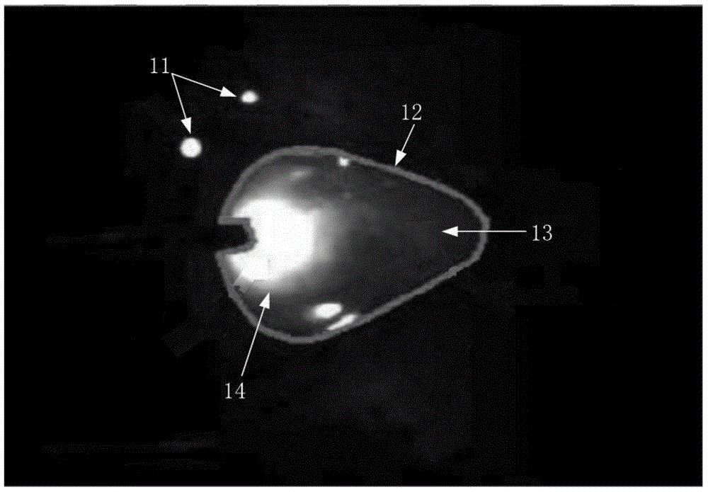
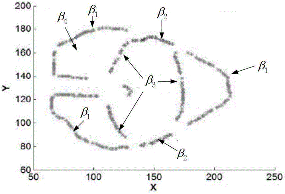
[0041] 1) Model the regions and edges of the melt pool image separately. When modeling image regions, see figure 1 , figure 2 , where 11 is solder splash, 12 is edge of molten pool, 13 is molten pool, and 14 is arc light. Divide the image region into interior regions p in (x) and the outer region p out (x), combined with its grayscale histogram features, to model the inner and outer regions as a Gaussian mixture model:

[0042] p ( x ) = Σ i = 1 N π i ...


PUM


Abstract

The embodiment of the invention discloses a passive visual system-based molten pool edge extraction method. A region and an edge in a molten pool image acquired by a passive visual system are modeled respectively, the two models are fused into a region-based active contour model and an edge-based active contour model respectively, the two active contour models are combined, and the combined active contour models are solved to accurately extract the edge of a molten pool in real time and provide useful information for the regulation of welding parameters in an automatic welding process.

Description

technical field [0001] The invention relates to a melting pool edge extraction method based on a passive vision system, in particular to a melting pool edge extraction method based on a passive vision system composed of a common CCD camera and an optical filter. Background technique [0002] Achieving automated welding can improve productivity and product quality. At present, automatic welding is facing two challenges: first, the welding process is complex and difficult to establish a model to describe it; second, there is a lack of suitable sensors to extract sufficient information, which is mainly the information of the edge of the weld and the edge of the molten pool. [0003] Obtaining information on the edge of the molten pool is a critical step for automatic welding technology. Because the molten pool edge information controls the welding parameters in the automatic welding process. At present, the technologies for obtaining edge information of molten pool usually in...

Claims


Application Information

Patent Timeline
IPC IPC(8): G06T7/00
CPCG06T7/0004G06T7/13G06T2207/30152
Inventor 范衠余泽峰容毅标林惠标李文姬
Owner SHANTOU UNIV
Why Eureka
Try Eureka