Permanent magnet contactor operating mechanism with trip safety device

A technology of safety device and operating mechanism, applied in electromagnetic relays, electromagnetic relay details, relays, etc., to achieve the effect of eliminating potential safety hazards

Active Publication Date: 2016-08-24
WENZHOU UNIVERSITY
View PDF3 Cites 0 Cited by
  • Summary
  • Abstract
  • Description
  • Claims
  • Application Information

AI Technical Summary

Problems solved by technology

[0004] Aiming at the deficiencies of the prior art, the present invention provides a permanent magnet contactor operating mechanism with a tripping safety device, which can forcefully break the contactor through the tripping safety device when the original coil cannot work normally. Iron core and static iron core, thus effectively eliminating potential safety hazards

Method used


Image

  • Permanent magnet contactor operating mechanism with trip safety device
  • Permanent magnet contactor operating mechanism with trip safety device
  • Permanent magnet contactor operating mechanism with trip safety device

Examples


Embodiment Construction

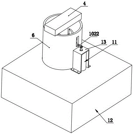
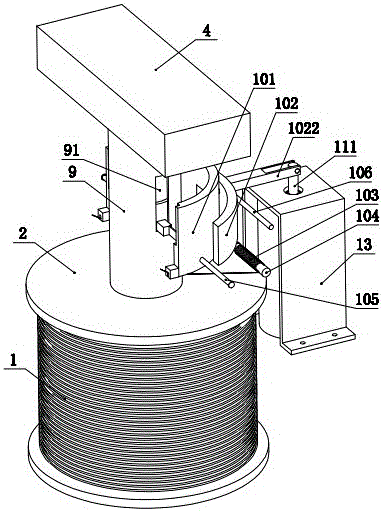
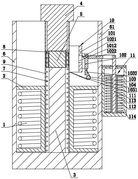
[0016] Such as figure 1 , 2 , 3, 4, 5, and 6 show a permanent magnet contactor operating mechanism with a trip safety device, including a coil 1, a coil frame 2, a static iron core 3, a moving iron core 4, and a permanent magnet 5. The yoke 6, the reaction force spring 7, the reaction force spring pressure sleeve 8, and the reaction force spring cover 9, the yoke 6 is a U-shaped structure, and the coil 1 is wound on the coil frame 2 and correspondingly located On the inner bottom surface of the U-shaped magnetic yoke 6, the static iron core 3 is penetrated in the coil frame 2, and the axial lower end of the static iron core 3 is connected with the inner bottom surface of the U-shaped magnetic yoke 6, and the described static iron core 3 The permanent magnet 5 is fixed on the axially upper end surface of the static iron core 2, and the outer coaxial sleeve of the permanent magnet 5 is provided with a reaction force spring pressure sleeve 8, and the described reaction force spr...


PUM


Abstract

The invention discloses a permanent magnetic contactor operating mechanism provided with a tripping security device. The permanent magnetic contactor operating mechanism comprises a coil, a coil frame, a fixed iron core, a movable iron core, a permanent magnet, a magnetic yoke, a counterforce spring, a counterforce spring pressing sleeve and a counterforce spring outer cover, wherein the tripping security device is arranged between the movable iron core and the permanent magnet, and comprises an inner arc-shaped sleeve, an outer arc-shaped sleeve, a torsion spring, a torsion spring rotary shaft, a hinged rotary rod of the inner arc-shaped sleeve and a hinged rotary rod of the outer arc-shaped sleeve. With the adoption of the structure, the tripping security device is additionally arranged, stores energy in a normal attraction process of the movable iron core and the fixed iron core and releases the stored energy once the movable iron core and the fixed iron core cannot be separated through original coils after the movable iron core and the fixed iron core attract, so that the movable iron core and the fixed iron core are forcedly separated and the purpose of eliminating potential safety hazards is achieved.

Description

technical field [0001] The invention relates to a permanent magnet contactor, in particular to a permanent magnet contactor operating mechanism with a trip safety device. Background technique [0002] At present, a permanent magnet contactor usually includes a coil, a coil frame, a static iron core, a moving iron core, a permanent magnet, a yoke, a reaction force spring, a reaction force spring compression sleeve, and a reaction force spring cover. The yoke is U-shaped structure, the coil is wound on the coil frame and correspondingly located on the inner bottom surface of the U-shaped yoke, the static iron core is installed in the coil frame, and the axial lower end of the static iron core is in line with the U-shaped The inner bottom surface of the yoke is connected and fixed, and the permanent magnet is fixed on the axial upper end surface of the static iron core. on the static iron core, and the axial ends of the reaction force spring are in contact with the reaction fo...

Claims


Application Information

Patent Timeline
Patent Type & Authority Patents(China)
IPC IPC(8): H01H50/64H01H50/16
CPCH01H50/16H01H50/643
Inventor 舒亮许成文吴桂初梁步猛吴浪
Owner WENZHOU UNIVERSITY
Why Eureka
Try Eureka