Dampproof electric power distribution cabinet favorable for water drainage

A technology for power distribution cabinets and drainage channels, which is applied to the substation/power distribution device shell, electrical components, substation/switch layout details, etc., and can solve problems such as insufficient cabinet door strength, dangerous electrical equipment, and large volume of power distribution cabinets. Achieve the effect of good moisture absorption, avoid safety threats, and reduce the possibility

Inactive Publication Date: 2015-04-29
GUIZHOU CHANGTONG ELECTRIC
View PDF8 Cites 3 Cited by
  • Summary
  • Abstract
  • Description
  • Claims
  • Application Information

AI Technical Summary

Problems solved by technology

[0002] Power distribution cabinets are often installed in outdoor environments. For areas with high humidity, moisture-proof design for power distribution cabinets is required. At present, moisture-proof depends on fans alone, but the area of ​​action of fans is limited. For environments with very high humidity, fans cannot play a role. Good overall moisture-proof effect, even water vapor will condense on the inner wall and top of the power distribution cabinet. It is very dangerous for electrical equipment
[0003] At the same time, the power distribution cabinet is generally relatively large in size, and the strength of the cabinet door is not enough. The traditional method is to use reinforcing ribs alone, which occupy most of the space of the cabinet door. If desiccant needs to be placed on the cabinet door, additional design is required. Dedicated deployment device

Method used


Image

  • Dampproof electric power distribution cabinet favorable for water drainage
  • Dampproof electric power distribution cabinet favorable for water drainage
  • Dampproof electric power distribution cabinet favorable for water drainage

Examples


Embodiment Construction

[0027] Embodiments of the present invention will be described below with reference to the drawings.

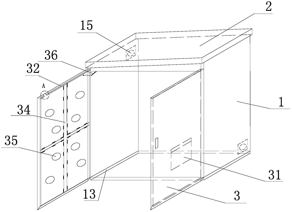
[0028] The invention provides a power distribution cabinet which is moisture-proof and good for drainage, such as figure 1 As shown, the power distribution cabinet includes a cabinet body 1 and a top cover 2 and a cabinet door 3 arranged on the cabinet body 1 .

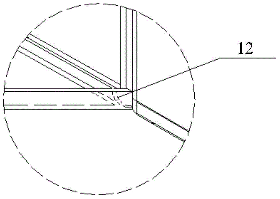
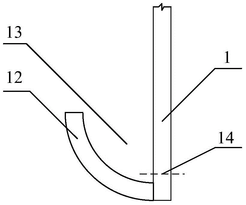
[0029] The bottoms of the three inner walls of the cabinet 1 are respectively provided with laterally extending cabinet drainage channels 13 , and the cabinet body at the position of the cabinet drainage channels 13 is provided with cabinet drainage holes 14 . In this embodiment, the drainage channel of the cabinet body is realized by using 1 / 4 round pipe combined with the wall surface. like figure 2 As shown, the 1 / 4 round pipe 12 has two straight sides and two arc sides, and the two ends can be provided with stoppers or blocked by other structures in the cabinet to prevent water from flowing out. like image 3 ...


PUM


Abstract

The invention discloses a dampproof electric power distribution cabinet which is favorable for water drainage. Not only is the electric power distribution cabinet strengthened, but also the problem of dampness is solved, and besides, the possibility that water drops flow onto the ground in the cabinet along the wall surface so as to damage electrical equipment is reduced. A cabinet body water drainage passage is arranged at the bottom of the inner wall surface of a cabinet body, and the inner wall surface of a top cover is a tilting plane; two fans are arranged and distributed on the upper side surface and the lower side surface which are opposite at the back of the cabinet body, reinforcing ribs which are arranged in a crossed manner and reinforcing blocks which are arranged along the diagonal lines of the cabinet bodies are arranged in each cabinet door; each reinforcing block comprises a body and a closed cover, wherein the bodies are formed by buckling hollow hemispherical casings on the cabinet doors, and the closed covers which can be opened and closed are mounted at the bottom openings in the bodies, so that an unpackaged drying agent is loaded in the bodies through top openings; through holes are formed in the upper half parts of the bodies; atmospheric pressure pull rods connected with the cabinet body are respectively arranged at the upper parts of the cabinet doors; right angle trapezoid sealing strips are arranged on four sides of each cabinet door; non-woven fabric data bags which are fixed by nylon fastener tapes are arranged on the inner wall surfaces of the cabinet doors.

Description

technical field [0001] The invention relates to the technical field of power distribution cabinet design. Background technique [0002] Power distribution cabinets are often installed in outdoor environments. For areas with high humidity, moisture-proof design for power distribution cabinets is required. At present, moisture-proof depends on fans alone, but the area of ​​action of fans is limited. For environments with very high humidity, fans cannot play a role. Good overall moisture-proof effect, even water vapor will condense on the inner wall and top of the power distribution cabinet. It is very dangerous for electrical equipment. [0003] At the same time, the power distribution cabinet is generally relatively large in size, and the strength of the cabinet door is not enough. The traditional method is to use reinforcing ribs alone, which occupy most of the space of the cabinet door. If desiccant needs to be placed on the cabinet door, additional design is required. Sp...

Claims


Application Information

Patent Timeline
Patent Type & Authority Applications(China)
IPC IPC(8): H02B1/28H02B1/56
CPCH02B1/28H02B1/565
Inventor 张钊张晖李贵祥杨运富
Owner GUIZHOU CHANGTONG ELECTRIC
Why Eureka
Try Eureka