Balance compensation device of low-voltage power grid
A technology of balance compensation and low-voltage power grid, applied in the field of electric power, can solve the problems of three-phase unbalance of low-voltage power grid, and achieve the effect of solving the problem of three-phase unbalance.
- Summary
- Abstract
- Description
- Claims
- Application Information
AI Technical Summary
Problems solved by technology
Method used
Image
Examples
Embodiment 1
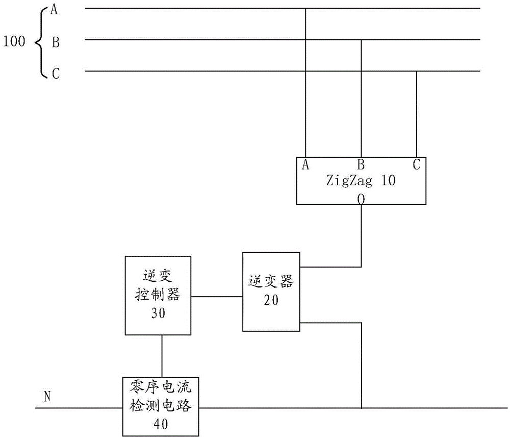
[0027] figure 1 A structural diagram of a balance compensation device for a low-voltage power grid provided in an embodiment of the present application.
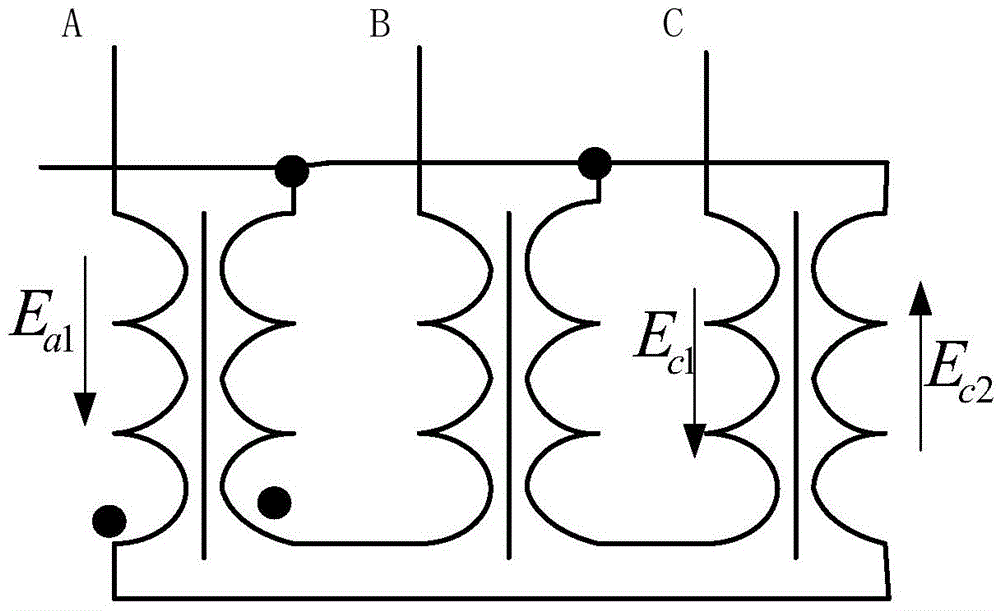
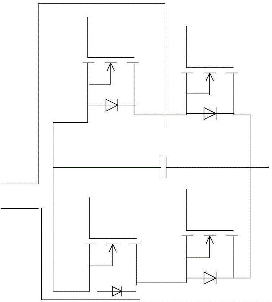
[0028] Such as figure 1 As shown, the balance compensation device provided by this embodiment includes a meander transformer 10 , a single-phase inverter 20 , a zero-sequence current detection circuit 40 and an inverter controller 30 .
[0029] The 10 three-phase input terminals of the meander transformer are connected to the three-phase phases of the low-voltage power grid 100. Since its impedance to the positive sequence current and the negative sequence current is very large, it will not affect its current, but its impedance to the zero sequence current is very large. Small, and basically 0, so zero-sequence current can flow easily.
[0030] One end of the output end of the single-phase inverter 20 is connected to the neutral line of the meander transformer 10 , and the other end is respectively connected to the neutral...
Embodiment 2
[0065] Figure 5 A structural diagram of a balance compensation device for a low-voltage power grid provided in another embodiment of the present application.
[0066] Such as Figure 5 As shown, the balance compensation device provided in this embodiment is based on the previous embodiment with the addition of a protection circuit 50 .
[0067] Because the output power of the single-phase inverter of this device has a certain limit, when the output current is too large, it will cause irreversible damage to the device. Fault, so the compensation current must be limited to protect the device. The protection circuit is used to cut off the connection between the meander transformer 10 and the low-voltage grid when the zero-sequence current exceeds the preset limit current, so as to protect the device. By examining the parameters of each component, the limit current of the device is preferably 60 amps.
PUM
 Abstract
Description
Claims
Application Information
 - R&D
- Intellectual Property
- Life Sciences
- Materials
- Tech Scout
- Unparalleled Data Quality
- Higher Quality Content
- 60% Fewer Hallucinations
Browse by: Latest US Patents, China's latest patents, Technical Efficacy Thesaurus, Application Domain, Technology Topic, Popular Technical Reports.
© 2025 PatSnap. All rights reserved.Legal|Privacy policy|Modern Slavery Act Transparency Statement|Sitemap|About US| Contact US: help@patsnap.com


