Reactive power compensation device and method

A compensation device and sub-compensation technology, applied in reactive power compensation, reactive power adjustment/elimination/compensation, circuit devices, etc., can solve the problems of insufficient reactive power compensation capacity, poor terminal voltage quality, and excessive reactive power consumption. , to achieve accurate and effective harmonic detection and compensation, reduce line loss, and overcome three-phase unbalance.

Pending Publication Date: 2021-03-09
STATE GRID SHANDONG ELECTRIC POWER +1
View PDF8 Cites 0 Cited by
  • Summary
  • Abstract
  • Description
  • Claims
  • Application Information

AI Technical Summary

Problems solved by technology

The characteristics of these lines are: long power supply radius, high reactive power consumption, low power factor, large line loss, and poor terminal voltage quality
[0006] According to statistical data, heavy-duty lines and low-voltage lines still occupy a considerable proportion. Compensation through capacitors is necessary to improve power quality and reduce losses; the capacity of reactive power compensation is insufficient. The power compensation device is relatively insufficient, the reactive power loss is large, and the voltage qualification rate is relatively low

Method used


Image

  • Reactive power compensation device and method
  • Reactive power compensation device and method
  • Reactive power compensation device and method

Examples


Embodiment 1

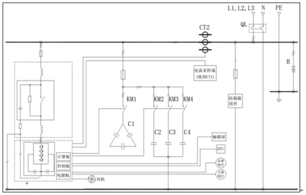
[0026] Such as figure 1 As shown, a reactive power compensation device includes a main circuit and a control system, the main circuit is a compensation current generation circuit, including sequentially connected LCL units and three-level converter modules; the control system includes a computing board and control board; the calculation board is used for data acquisition and processing, and transmits the calculation data to the control board; the control board generates control signals for active and passive units according to the received calculation data, and transmits the control signals to the main circuit , to control each unit of the main circuit.

[0027] Further, the main circuit includes a bus bar, a common compensation capacitor connected to the bus bar, a sub-compensation capacitor, an LCL unit and a three-level converter module. One end of the LCL unit is connected to the bus bar of the main circuit after being connected with a fuse, and the other end is connected...

Embodiment 2

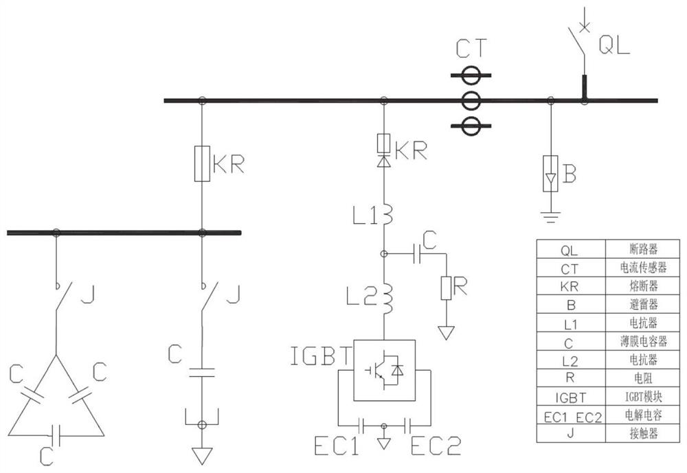
[0072] The present disclosure also provides a method for using the reactive power compensation device described in the above-mentioned embodiments, which is connected to the power grid through sequentially connected LCL units and three-level converter modules; by adjusting the phase and amplitude of the output voltage in real time, The reactive current absorbed or emitted by the circuit can be changed to realize dynamic reactive power compensation.


PUM


Abstract

The invention provides a reactive power compensation device, and the device comprises a main circuit, wherein the main circuit is a compensation current generation loop and comprises an LCL unit and athree-level conversion module group which are connected in sequence; the main circuit is connected to a power grid through an LCL unit and a three-level converter module which are connected in sequence; by adjusting the phase and amplitude of the output voltage in real time, the reactive current absorbed or emitted by the circuit can be changed, and dynamic reactive compensation is realized. Dynamic compensation is tracked in real time through a control system, harmonic current is detected in real time through the harmonic current compensation technology based on the instantaneous reactive power theory, dynamic compensation of the harmonic current is achieved through instantaneous current tracking control, load harmonic changes are automatically tracked, and high controllability and rapidresponsiveness are achieved. And the compensation performance is excellent, and is not influenced by the system impedance; the risk of resonance with the system impedance can be eliminated, and system resonance caused by harmonic waves in a power supply system can also be suppressed.

Description

technical field [0001] The present disclosure relates to the field of power utilization security of a distribution network, and specifically relates to a reactive power compensation device and method. Background technique [0002] In recent years, power companies have continuously increased investment in distribution network construction, comprehensively promoted lean management of distribution network, and improved the level of automation / intelligence of distribution network. Overall, it has formed the characteristics of strong structure, flexible operation mode, high power supply capacity and power supply reliability. distribution network. However, due to some reasons, the distribution network still has the problems of high distribution transformer loss in some areas, too high or too light load, and there are also problems such as relatively insufficient reactive power and high line loss in the low-voltage station area, which has the potential to further tap the potential ...

Claims


Application Information

Patent Timeline
IPC IPC(8): H02J3/18H02J3/01
CPCH02J3/1864H02J3/01Y02E40/40Y02E40/30
Inventor 谢辰璐李超王兴帅王福军王东阳毛永强鞠鹏徐铖边文浩薛洁
Owner STATE GRID SHANDONG ELECTRIC POWER
Why Eureka
Try Eureka