Passive component with temperature compensation and electronic device using same

An electronic device and negative temperature coefficient technology, applied in the direction of output power conversion devices, electrical components, high-efficiency power electronic conversion, etc., to achieve the effect of increasing output voltage, reducing partial pressure difference, and accurate sensing results

Active Publication Date: 2017-04-12
ACER INC
View PDF5 Cites 0 Cited by
  • Summary
  • Abstract
  • Description
  • Claims
  • Application Information

AI Technical Summary

Problems solved by technology

[0004] The present invention provides a passive component with temperature compensation and an electronic device using it to solve the problems mentioned in the prior art

Method used


Image

  • Passive component with temperature compensation and electronic device using same
  • Passive component with temperature compensation and electronic device using same

Examples


Embodiment Construction

[0053] Reference will now be made in detail to the exemplary embodiments of the present invention, examples of which are illustrated in the accompanying drawings. In addition, elements / members with the same or similar numbers used in the drawings and embodiments are used to represent the same or similar parts.

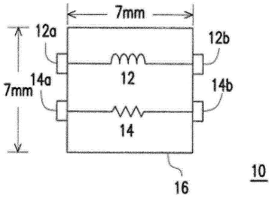
[0054] After careful research, the inventors of the present application found that the reason why the current technology uses NTC resistors to measure the voltage difference across the inductor is inaccurate because: the NTC resistor and the inductor are not in direct contact and there is air. Air is one of the media for heat dissipation. When the negative temperature coefficient resistor reacts the heat of the inductor across the air, part of the heat will be dissipated with the air. Therefore, the NTC resistor cannot accurately compensate the error caused by the current flowing through the inductor.

[0055] figure 1 It is a configuration diagram of a passive comp...


PUM


Abstract

The invention provides a passive element with temperature compensation and an electronic device using it. The electronic device includes a central processing unit, a filter and a power conversion circuit. Filters consist of passive components and variable resistors. Passive components include inductors and negative temperature coefficient resistors. The negative temperature coefficient resistor is placed in the package in contact with the surface of the inductor. The power conversion circuit provides current information to the central processing unit according to the divided voltage difference of the filter. The power conversion circuit controls the output voltage through the filter according to the first control signal of the central processing unit, so as to provide the output voltage. The electronic device may also include an embedded controller. The embedded controller controls the variable resistor according to the second control signal of the central processing unit.

Description

technical field [0001] The invention relates to a passive component, in particular to a passive component with temperature compensation and an electronic device using it. Background technique [0002] The power conversion circuit provides a DC output voltage to the central processing unit through the inductor. In order to calculate the power consumed by itself, the central processing unit needs to obtain the current flowing through the inductor indirectly through the sensing circuit. Since the inductor itself has parasitic resistance, the sensing circuit uses the voltage difference across the inductor to convert the value of the flowing current. [0003] In addition, when the inductor is flowing current, it will generate heat and increase the resistance value of the parasitic resistance. Existing methods may add negative temperature coefficient resistors. However, the negative temperature coefficient resistor cannot accurately compensate the error caused by the inductor d...

Claims


Application Information

Patent Timeline
Patent Type & Authority Patents(China)
IPC IPC(8): H02M1/42
CPCH02M3/156H02M3/1566Y02B70/10
Inventor 李柏钰阮冠旗蔡孟杰
Owner ACER INC
Why Eureka
Try Eureka