Image processing apparatus and image processing method

An image processing device and image technology, applied in image data processing, image communication, graphics and image conversion, etc., can solve the problems of increasing the moving distance of the driver's line of sight and difficulty in understanding the corresponding relationship between objects

Inactive Publication Date: 2015-04-29
FUJITSU LTD
View PDF9 Cites 6 Cited by
  • Summary
  • Abstract
  • Description
  • Claims
  • Application Information

AI Technical Summary

Problems solved by technology

That is, in order to confirm the blind spot, the driver needs to check multiple monitors or mirrors that are physically separated from each other, which causes the driver's line of sight to move a lot
[0006] In addition, when blind spots are confirmed through multiple monitors or mirrors, it is difficult to know the correspondence of objects displayed on the monitors or mirrors
The problem created by this situation is that acknowledging the surrounding environment while operating the vehicle requires skill and is not an easy task

Method used


Image

  • Image processing apparatus and image processing method
  • Image processing apparatus and image processing method
  • Image processing apparatus and image processing method

Examples


Embodiment 1

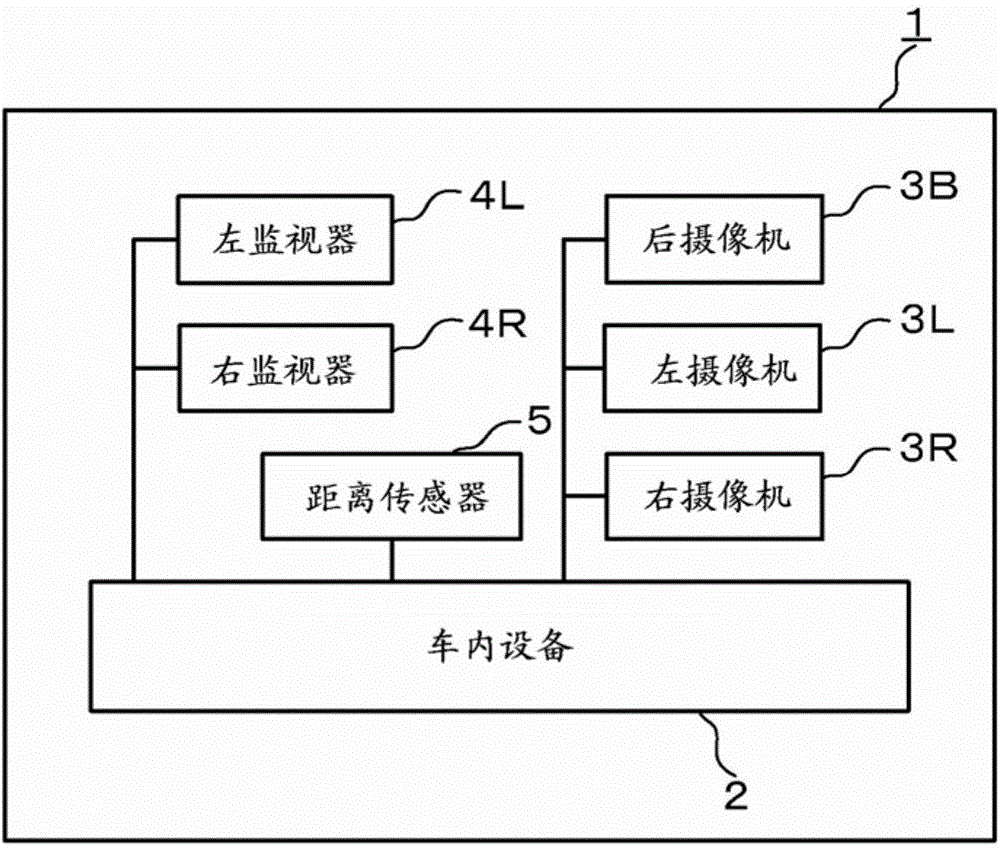
[0040] figure 1 is a view illustrating an exemplary configuration of the in-vehicle system 1 according to Embodiment 1. refer to figure 1 , the in-vehicle system 1 includes: an in-vehicle device 2 as an image processing device, a plurality of cameras 3 , one or more monitors 4 , and a distance sensor 5 . Such as figure 1 As illustrated in , the in-vehicle device 2 is connected to a plurality of cameras 3 , one or more monitors 4 and a distance sensor 5 .

[0041] In the following description, Embodiment 1 will be described by taking an example of a blind spot that exists in the field of view on the rear side of the vehicle and is blocked by the vehicle body.

[0042] The camera 3 includes an imaging device such as a CCD (Charge Coupled Device), COM (Complementary Metal-Oxide Semiconductor), MOS (Metal-Oxide Semiconductor), and the like. The camera 3 captures images of the vicinity of the vehicle at, for example, 30 fps (frame per second) and sequentially stores the capture...

Embodiment 2

[0160] A method of generating a occlusion image of a reference vehicle body when the in-vehicle system 1 according to Embodiment 1 is equipped in a mass-produced vehicle will be described by Embodiment 2.

[0161] Figure 22 is a functional block diagram illustrating a configuration example of the in-vehicle device 2 according to Embodiment 2. The vehicle according to Embodiment 2 except that the control unit 40 also serves as the reference vehicle body occlusion image generation unit 49 and the ideal arrangement parameters of the right camera 3R and the left camera 3L and the ideal vehicle body occlusion image are stored in the data area of ​​the storage unit 10. The in-vehicle device 2 has the same basic configuration as the in-vehicle device in Embodiment 1. In addition, some of the usual functional units of the controller 40 (for example, the transformation matrix generation unit 43 ) are slightly different from those in Embodiment 1 in function.

[0162] The ideal arran...

Embodiment 3

[0187] A method of generating an occlusion image of a reference vehicle body of a mass-produced vehicle based on vehicle body shape data will be described through Embodiment 3.

[0188] The in-vehicle device 2 according to Embodiment 3 has the same basic configuration as the in-vehicle device in Embodiment 2, except that vehicle body shape data instead of an ideal body occlusion image is stored in the data area of ​​the storage unit 10 . In addition, some of the general functional units of the controller 40 (for example, the transformation matrix generation unit 43 and the reference vehicle body occlusion image generation unit 49 ) are slightly different from those in Embodiment 2 in function.

[0189] Body shape data is, for example, three-dimensional polygonal data defined in the vehicle coordinate system that models the shape of the vehicle, such as Figure 25 exemplified in .

[0190] In addition to the above-described processing in Embodiment 1, the transformation matrix...


PUM


Abstract

An image processing apparatus includes a first field-of-view converting unit configured to convert an image of a first camera, which is equipped in a vehicle and arranged to include a portion of a vehicle body in an image capturing range, into an image having an arbitrary field-of-view within a field-of-view of the first camera; a second field-of-view converting unit configured to convert a blind spot image, which is an image of a second camera capturing an image of a peripheral environment acting as a blind spot by the first camera, into the blind spot image having the same field-of-view as the field-of-view of the image obtained after the conversion by the first converting unit; and a compositing unit configured to compose a region corresponding to the blind spot image obtained by the second converting unit to the region of the vehicle body of the image obtained by the first converting unit.

Description

technical field [0001] The embodiments described herein relate to an image processing device, an image processing method, and a program. Background technique [0002] When the driver is driving the vehicle, there is a blind spot in the driver's field of view that is blocked by the vehicle body or the like and cannot be directly seen by the driver. As a method of ensuring visibility to the rear of the vehicle, interior mirrors and side mirrors within blind spots are installed in the vehicle. [0003] In addition, in recent years, various devices such as rear cameras and front cameras have been developed to supplement the visibility of blind spots (see, for example, Patent Document 1). It is expected that a CMS (Camera Monitor System) under the standardization of ISO 16505 for displaying an image obtained by photographing a vehicle rear side position on a monitor will be promoted as a substitute for a side mirror. [0004] For CMS, the field of view displayed on the monitor ...

Claims


Application Information

Patent Timeline
Patent Type & Authority Applications(China)
IPC IPC(8): H04N7/18
CPCG06T3/4038B60R1/08G06T3/40G06T3/4084H04N5/262B60R11/04B60R2300/105B60R2300/202B60R2300/303
Inventor 清水诚也
Owner FUJITSU LTD
Why Eureka
Try Eureka