Oil filter for treating dirty oil in electrical cabinet profile bending machine

A cabinet profile and bending machine technology, applied in the direction of filtration circuit, filtration separation, liquid degassing, etc., can solve the problem of inconspicuous filtration effect

Active Publication Date: 2015-05-06
SICHUAN XINGZHI ZHIHUI INTPROP OPERATION CO LTD
View PDF6 Cites 5 Cited by
  • Summary
  • Abstract
  • Description
  • Claims
  • Application Information

AI Technical Summary

Problems solved by technology

Aiming at the problem that the filtering effect of hydraulic oil or lubricating oil is not obvious in the prior art, the quality and filtering efficiency of the filtered oil can be further improved; when the present invention works, the oil is injected through the beginning of the oil guide pipe, and after flowing into the filter When inside the tank, the heater starts to heat the part of the oil guide pipe located in the heating chamber at a high temperature, so that the volatile gas in the oil liquid or the soluble impurity gas such as water vapor will come out, and when the liquid-gas mixture enters the end of the oil guide pipe, inject oil When inside the column, the two side walls of the oil injection column are provided with through holes communicating with the hollow wing plates, and the oil injection column is rotated and set on the oil guide pipe, so when the oil is injected into the oil injection column at a certain rate, the oil injection The co

Method used


Image

  • Oil filter for treating dirty oil in electrical cabinet profile bending machine
  • Oil filter for treating dirty oil in electrical cabinet profile bending machine
  • Oil filter for treating dirty oil in electrical cabinet profile bending machine

Examples


Example Embodiment

[0021] Example 1

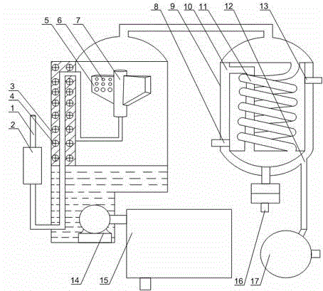
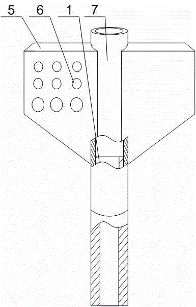
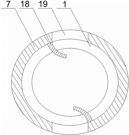
[0022] Such as Figure 1~Figure 3 As shown, this embodiment includes a filter tank 3 and an oil guide pipe 1 that penetrates the outer wall of the filter tank 3 and is placed at the upper end of the inner part of the filter tank 3. The top end of the filter tank 3 communicates with the condensate tank 9 and is fixed on the side wall of the filter tank 3 There is a heating cavity, the oil guide pipe 1 penetrates the heating cavity, and a heater 4 is installed in the heating cavity, and an oil injection column 7 connected to the oil guide pipe 1 is rotatably arranged at the end of the oil guide pipe 1. Hollow wing plates 5 are fixed on both sides of the two wing plates 5, a plurality of injection holes 6 are opened on the opposite sides of the two wing plates 5, and the fuel injection column 7 is provided with a through hole communicating with the fuel injection hole 6. An oil pump 14 is fixed at the bottom of the tank 3, and the oil outlet end of the oil pump 1...


PUM


Abstract

The invention discloses an oil filter for treating dirty oil in an electrical cabinet profile bending machine. The oil filter comprises a filter tank and an oil guide pipe, wherein the oil guide pipe penetrates through the outer wall of the filter tank and is placed at the upper end inside the filter tank; the top end of the filter tank is communicated with a condensation tank; a heating chamber is fixedly formed in the side wall of the filter tank, the oil guide pipe penetrates through the heating chamber, and a heater is mounted in the heating chamber; an oil injection column communicated with the oil guide pipe is rotationally arranged at the end part of the oil guide pipe, hollow wing plates are fixed on the two sides of the oil injection column, and a plurality of oil injection holes are formed in the opposite sides of the two wing plates; through holes communicated with the oil injection holes are formed in the oil injection column; an oil pump is fixed at the bottom of the filter tank, and the oil outlet end of the oil pump penetrates through the filter tank and is connected with a magnetic filter. Gas enters the condensation tank from the top of the filter tank and is newly fluidized under the condensation effect of the condensation tank to be convenient for centralized collection and treatment, and the purposes of improving the absorption of impurities in liquid when oil for bending is filtered and further improving the filtering efficiency of the oil for bending are further achieved.

Description

technical field [0001] The invention relates to an electric cabinet profile punching device, in particular to an oil filter used for treating dirty oil of an electric cabinet profile bending machine. Background technique [0002] During the processing of the electrical cabinet frame, the strip or plate-shaped profiles are usually stamped, punched and bent, and then the frame is welded as a whole. In the production workshop, the hydraulic oil or lubricating oil of the device itself will be reduced due to overflow during the use of the punching machine used for punching and punching strip or plate-shaped profiles, so it must be regularly replenished to the device. There is a large amount of oil, which undoubtedly increases the production cost, so how to use the overflowing hydraulic oil to reduce the use cost of the device is very important. At present, the oil filter is widely used in the purification of hydraulic oil, hydraulic transmission oil, gear oil, gasoline engine oi...

Claims


Application Information

Patent Timeline
IPC IPC(8): B01D36/00B01D19/00C10M175/00
Inventor 陈怀之王刚聂海涛张仁友胡国波
Owner SICHUAN XINGZHI ZHIHUI INTPROP OPERATION CO LTD
Why Eureka
Try Eureka