
Hydraulic dynamic bending machine

A bending machine and hydraulic technology, applied in metal processing, metal processing equipment, forming tools, etc., can solve problems such as overrun, insufficient force, and impact on the quality of formed plates, so as to achieve precise control, quality assurance, and Even force and precise effect

Inactive Publication Date: 2015-05-06
江苏久日数控机床有限公司
View PDF6 Cites 6 Cited by
  • Summary
  • Abstract
  • Description
  • Claims
  • Application Information

AI Technical Summary

Problems solved by technology

However, it cannot precisely control the position of the upper and lower dies during the bending process, which leads to insufficient force or over-limited force on the plate during the bending process, which affects the quality of the final formed plate

Method used


Image

  • Hydraulic dynamic bending machine

Examples


Embodiment Construction

[0011] The present invention will be described in further detail below in conjunction with the accompanying drawings.

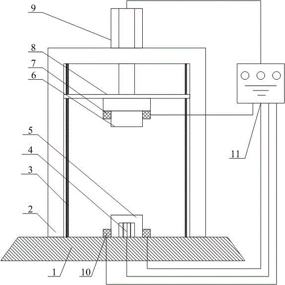
[0012] Such as figure 1 As shown, in the hydraulic bending machine of the present invention, the frame 2 is in the shape of an inverted U, and is fixedly mounted on the base 1 . The guide post 3 is located in the frame 2, and the guide post 3 is two vertically set up on both sides inside the frame 2. The hydraulic jack 9 is erected on the top of the frame 2, the output shaft of the hydraulic jack 9 passes through the frame 2 downward, and the output shaft of the hydraulic jack 9 is fixedly connected with the connecting block 8. The hydraulic jack 9 is connected to a control unit 11, and the control unit 11 controls the movement of the output shaft.

[0013] Both ends of the connecting block 8 are provided with openings corresponding to the guide post 3 , the connecting block 8 is sleeved on the guide post 3 , and the connecting block 8 can move up and down ...


PUM


Abstract

The invention discloses a hydraulic dynamic bending machine, and belongs to the field of machining. The hydraulic dynamic bending machine comprises an inverted U-shaped rack, a hydraulic driving device, a connecting block, an upper die, a lower die, a control unit and two guide posts, wherein the hydraulic driving device is erected at the top part of the rack and is connected with the control unit, the two guide posts are respectively arranged at two side edges in the rack, the connecting block is arranged at the inner side of the rack and is connected with the lower end of the hydraulic driving device, the two guide posts can be respectively inserted into two ends of the connecting block, the connecting block can move up and down along the guide posts, the upper die is connected below the connecting block, the lower die is arranged right under the upper die, a distance sensing device is arranged between the upper die and the lower die, and the distance sensing device is connected with the control unit. Through the matching of an infrared transmitter and an infrared sensor between the upper die and the lower die, the distance between the upper die and the lower die can be accurately controlled, thus the stress on a plate during a bending process is more uniform and accurate, and the quality of finished plates is ensured.

Description

technical field [0001] The invention relates to a bending machine, in particular to a hydraulic bending machine, which belongs to the field of mechanical processing. Background technique [0002] Bending machine is a commonly used mechanical processing equipment, which is widely used in the manufacture of various steel structural parts. The existing hydraulic bending machine pushes the upper and lower molds to close by using the hydraulic jack, and realizes bending through the transformation of the molds. It is easy to operate, high in production efficiency, and greatly reduces the labor intensity of workers. However, it cannot precisely control the position of the upper and lower dies during the bending process, which leads to insufficient or over-limited force on the plate during the bending process, which affects the quality of the final formed plate. Contents of the invention [0003] The technical problem to be solved by the present invention is to overcome the defec...

Claims


Application Information

Patent Timeline
Patent Type & Authority Applications(China)
IPC IPC(8): B21D37/10B21D5/06B21C51/00
CPCB21C51/00B21D5/06B21D37/10
Inventor 俞圣平
Owner 江苏久日数控机床有限公司
Learn More