Automotive transmission gear shaving jig

A technology for automotive transmissions and gears, which is applied to gear teeth manufacturing devices, belts/chains/gears, gear teeth, etc. It can solve the problems of reducing gear shaving processing efficiency, cumbersome gear installation and removal operations, and improve processing efficiency. , Easy and fast disassembly operation

Active Publication Date: 2018-09-21
CHONGQING HUARUI STANDARD COMPONENT MFG CO LTD
View PDF6 Cites 0 Cited by
  • Summary
  • Abstract
  • Description
  • Claims
  • Application Information

AI Technical Summary

Problems solved by technology

The above fixtures often have the following problems: when installing the gear, the gear needs to be installed on the mandrel first and fixed by the positioning sleeve and the ferrule, and then the machine tool is operated to make the top column of the machine tool retreat, and then the mandrel is placed between the two top columns. At last, the top column advances to support the two ends of the mandrel, and then the gear can be processed; when the gear is disassembled, the machine tool needs to be operated to make the top column retreat, and then the mandrel is removed from between the two top columns, and then the ferrule is removed. to remove the gear
The installation and removal of the above-mentioned gears is cumbersome, which greatly reduces the processing efficiency of gear shaving

Method used


Image

  • Automotive transmission gear shaving jig
  • Automotive transmission gear shaving jig
  • Automotive transmission gear shaving jig

Examples


Embodiment Construction

[0015] Below in conjunction with accompanying drawing and specific embodiment the present invention will be described in further detail:

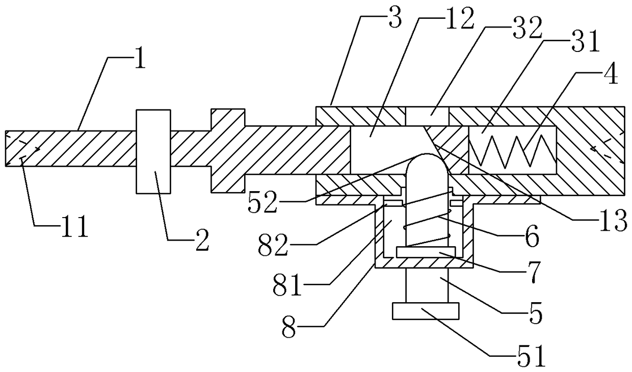
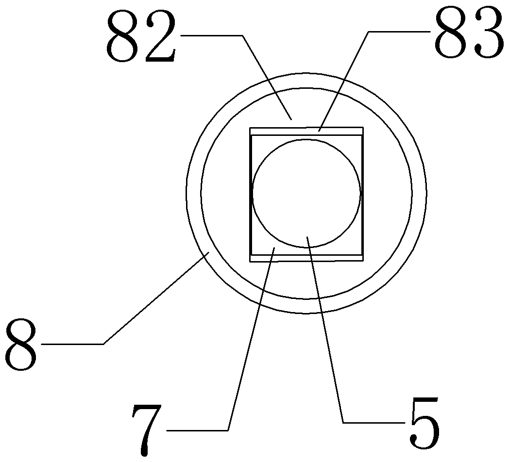
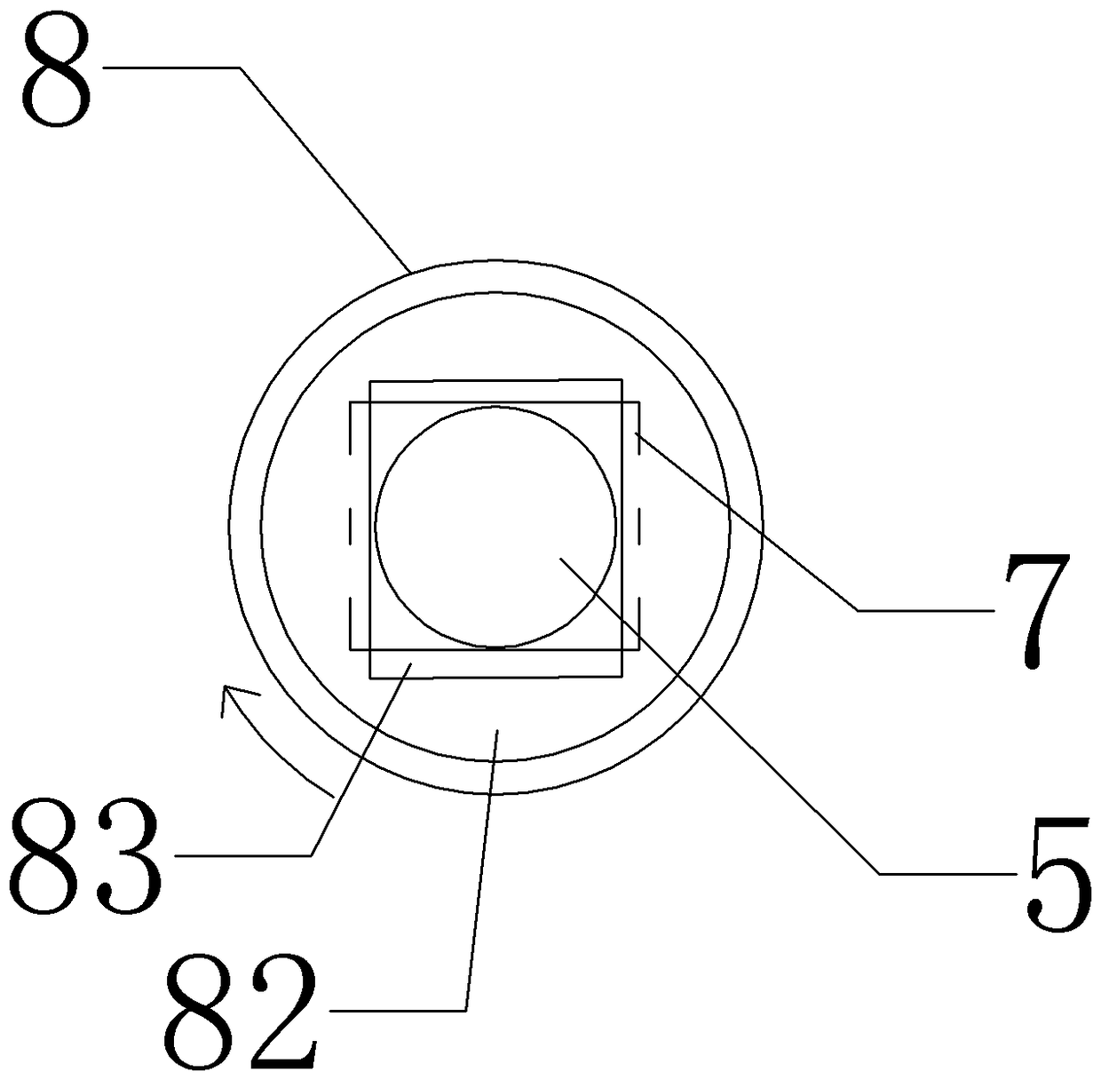
[0016] like figure 1 The automotive transmission gear shaving jig shown includes a stepped mandrel 1, a conical groove 11, a first elongated hole 12, an inclined hole wall 13, a ferrule 2, a connecting seat 3, a guide cavity 31, and a first through hole 32. Compression spring 4, rod-shaped button 5, button handle 51, spherical end 52, back-moving spring 6, clamping plate 7, support seat 8, support cavity 81 and chuck 82.

[0017] One end of the stepped mandrel 1 is provided with a conical groove 11, which is used for positioning the stepped mandrel at the top of the top column of the machine tool. The gear is sleeved into the small diameter section of the stepped mandrel through the conical groove 11 of the stepped mandrel 1, and one side is attached to the shaft. The shoulder is clamped by the shaft shoulder, and the ferrule 2 is set into...


PUM


Abstract

The invention provides a shaving clamp for an automotive transmission gear, wherein the shaving clamp is easy to operate. The clamp comprises a stepped mandrel, a conical groove is formed in one end of the stepped mandrel, a clamping sleeve is arranged on the stepped mandrel in a sleeving mode, a conical groove is formed in one end of a connecting base, a guide cavity is formed in the connecting base, the other end of the stepped mandrel is matched with a sliding sleeve of the connecting base, and a compressed spring is arranged between the bottom of the guide cavity and the stepped mandrel; a first long-strip-shaped hole is formed in the radial direction of the stepped mandrel, and the hole wall, located on one side of the compressed spring, of the first long-strip-shaped hole is the inclined hole wall; a first through hole and a second through hole are formed in the wall of the guide cavity, a supporting cavity is formed in a supporting base, a third through hole is formed in the bottom of the supporting cavity, the center connecting line of the first through hole, the second through hole and the third through hole is perpendicular to the axial direction of the stepped mandrel, one end of a rod-shaped button is a spherical surface end, the other end of the rod-shaped button is provided with a clamping plate, and the rod-shaped button penetrates through the first through hole, the first long-strip-shaped hole, the second through hole and the third through hole.

Description

technical field [0001] The invention relates to a machine tool fixture, in particular to an automobile transmission gear shaving fixture. Background technique [0002] The transmission used in automobiles is used to coordinate the speed of the engine and the actual driving speed of the wheels, change the transmission ratio, and expand the range of torque and speed of the driving wheels to adapt to changing driving conditions. And work under the condition of lower fuel consumption. The transmission is usually installed between the driving shaft and the driven shaft of the engine. The basic structure of the transmission includes a housing, a transmission part and an operating part. The housing is used to install and support all parts of the transmission and store lubricating oil. The transmission part includes shafts, bearings and multiple gears with different diameters. The transmission form is divided into Ordinary slip gear and planetary gear transmission. [0003] Durin...

Claims


Application Information

Patent Timeline
Patent Type & Authority Patents(China)
IPC IPC(8): B23F23/06
Inventor 蔡良华
Owner CHONGQING HUARUI STANDARD COMPONENT MFG CO LTD
Why Eureka
Try Eureka