Crosshead shoe third shaft group mechanism of center-moving lathe-milling machine tool

A cross-slide, shaft group technology, applied in metal processing machinery parts, other manufacturing equipment/tools, large fixed members, etc., can solve problems such as inability to realize complex parts, avoid resistance, high production efficiency, and reduce heat generation Effect

Inactive Publication Date: 2015-05-06
NANJING JIANKE MACHINERY
View PDF0 Cites 3 Cited by
  • Summary
  • Abstract
  • Description
  • Claims
  • Application Information

AI Technical Summary

Problems solved by technology

[0005] The technical problem solved by the invention is the problem that the existing rotary milling machine tool cannot realize the one-time processing and forming of complex parts, and the efficiency is not high

Method used


Image

  • Crosshead shoe third shaft group mechanism of center-moving lathe-milling machine tool
  • Crosshead shoe third shaft group mechanism of center-moving lathe-milling machine tool
  • Crosshead shoe third shaft group mechanism of center-moving lathe-milling machine tool

Examples


Embodiment 1

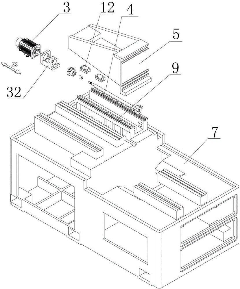
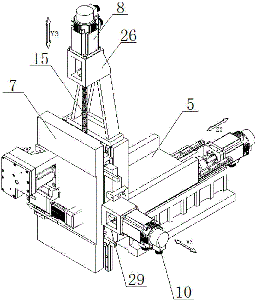
[0045] Such as Figure 1 to Figure 3 The mechanism of the third axis group of the cross slide on the center-type turning and milling machine shown includes the bed 1; the Z3 axis group, the X3 axis group and the Y3 axis group arranged on the bed 1, and the Z3 axis group Including the Z3-axis servo motor 3, the Z3-axis screw rod 4, the Z3-axis slide plate 5, the Z3-axis coupling and the Z3-axis servo motor seat 32 arranged on the bed 1 for installing the Z3-axis servo motor 3, the Z3-axis The axis servo motor 3 drives the Z3 axis slide plate 5 to slide back and forth along the Z axis direction on the bed 1 through the Z3 axis screw 4. The Z3 axis slide plate 5 is slidably installed on the bed 1, and the specific sliding is the The Z3 axis rail 9 is arranged on the top, the Z3 axis slider 12 matching with the Z3 axis rail 9 is arranged at the bottom of the Z3 axis slide plate 5, the Z3 axis nut is arranged at the bottom of the Z3 axis slide plate 5, and the Z3 axis screw rod 4 p...

Embodiment 2

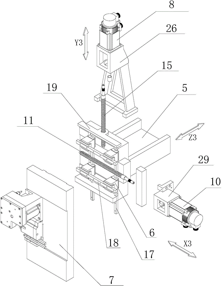
[0048] This embodiment is similar to Embodiment 1, the only difference is that the cross slider 6 is composed of an X3-axis slider, a Y3-axis slider, and a right-angled block connecting the X3-axis slider and the Y3-axis slider. The Y3 axis rail 17 is set, and the X3 axis rail 18 is arranged on the tool mounting plate 7. The Y3 axis slider and the X3 axis slider respectively form a sliding pair with the Y3 axis rail 17 and the X3 axis rail 18, and the slide seat 19 is fixed by On the two right-angle blocks adjacent to the left and right, the sliding seat 19 is fixed on the same side of the two cross sliders 6 adjacent to the left and right; in the present invention, the X3-axis slider, the Y3-axis slider and the right-angle block are fixed by bolts, Can also be welded. The other structures are the same as those in Embodiment 1, which can be compared with Embodiment 1 for details, and will not be described too much here.

[0049] When the present invention is applied to the ex...


PUM


Abstract

The invention discloses a crosshead shoe third shaft group mechanism of a center-moving lathe-milling machine tool. The crosshead shoe third shaft group mechanism comprises a Z3 shaft group arranged on a lathe bed, a Y3 shaft group and an X3 shaft group, wherein the Z3 shaft group comprises a Z3 shaft servo motor, a Z3 shaft screw rod and a Z3 shaft slide plate; the Z3 shaft slide plate is mounted on the lathe bed; the Z3 shaft screw rod is in thread connection with the Z3 shaft slide plate; one end of the Z3 shaft screw rod is connected with a transmission shaft of the Z3 shaft servo motor; the Y3 shaft group comprises a crosshead shoe which is glidingly arranged on the Z3 shaft slide plate, a Y3 shaft servo motor, a slide seat and a Y3 shaft screw rod; the Y3 shaft screw rod is in thread connection with the slide seat; one end of the Y3 shaft screw rod is connected with a transmission shaft of the Y3 shaft servo motor; the X3 shaft group comprises a tool mounting plate, an X3 shaft servo motor and an X3 shaft screw rod; the X3 shaft screw rod is in thread connection with the tool mounting plate; one end of the X3 shaft screw rod is connected with a transmission shaft of the X3 shaft servo motor. The crosshead shoe third shaft group mechanism has the beneficial effects that the problems that the machining and molding of a complicated part cannot be realized at one step by an existing center-moving lathe-milling machine tool and the efficiency is not high are solved.

Description

technical field [0001] The invention relates to a third shaft group mechanism of a cross slider on a center turning type turning and milling machine tool. Background technique [0002] In the existing centering machine market, there has been research on the technology of machine tool motion axes, and the most widely used one is the three-axis with positive axis structure consisting of X1 axis group, Y1 axis group, and Z1 axis group. Swivel type turning and milling machine tool (definition: the mechanism including linear rail, slide plate, screw, and servo motor is a group of axes); or, when the sub-axis structure is added with a Z2-axis group, it can be combined with the positive axis structure to form four axes Rotary turning and milling machine tools; or, when the auxiliary shaft is composed of X2 axis group and Z2 axis group, the auxiliary shaft structure is combined with the positive axis structure to form a five-axis rotating and milling machine tool; or, when the auxil...

Claims


Application Information

Patent Timeline
Patent Type & Authority Applications(China)
IPC IPC(8): B23Q1/62B23Q5/40B23P23/02
CPCB23Q1/62
Inventor 王建飞
Owner NANJING JIANKE MACHINERY
Why Eureka
Try Eureka