Tool for vertical lathe machining of ring-cone-shaped thin-walled part and application thereof

A thin-walled part and ring-tapered technology, which is applied in the field of thin-walled parts processing technology and equipment, can solve the problems of inability to ensure that parts do not slip, uniform gaps, and large shape errors.

Active Publication Date: 2015-05-06
WUHAN MARINE MACHINERY PLANT
View PDF6 Cites 41 Cited by
  • Summary
  • Abstract
  • Description
  • Claims
  • Application Information

AI Technical Summary

Problems solved by technology

[0006] However, the clamping device in the above technical solution is only suitable for the processing of straight cylindrical thin-walled parts with constant diameter. For tapered annular thin-walled parts, this kind of fixture cannot guarantee that the parts will not slip during processing; in addition, For the circumferential gap between the cylinder wall and the outer wall of the inner annular Huff block, the gap cannot be guaranteed to be uniform; at the same time, the left and right taper sleeves are often unable to be disassembled due to the tight combination of the tapered surfaces when disassembling after the clamping is completed; In particular, when processing the two ends of the part, since the free ends of the two ends of the part are longer, the rigidity of the two ends is insufficient and deformation is likely to occur, and vibration will occur during processing, which makes the overall processing accuracy worse. Low, large shape error

Method used


Image

  • Tool for vertical lathe machining of ring-cone-shaped thin-walled part and application thereof
  • Tool for vertical lathe machining of ring-cone-shaped thin-walled part and application thereof
  • Tool for vertical lathe machining of ring-cone-shaped thin-walled part and application thereof

Examples


Embodiment Construction

[0041] In order to make the object, technical solution and advantages of the present invention clearer, the present invention will be further described in detail below in conjunction with the accompanying drawings and embodiments. It should be understood that the specific embodiments described here are only used to explain the present invention, not to limit the present invention. In addition, the technical features involved in the various embodiments of the present invention described below can be combined with each other as long as they do not constitute a conflict with each other.

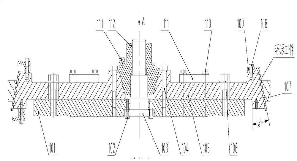
[0042] The technical equipment for processing the end of the annular thin-walled part in this embodiment includes a tooling base plate 101, a mandrel 103, a compression nut 112, a tapered block 113, a bulging slider 105, a limit pressure block 111, a pressure ring 107, Protect the pressure block 109 and the attached fasteners 108 .

[0043] Such as figure 1 , The specific connection form of th...


PUM


Abstract

The invention discloses a tool for vertical lathe machining of a ring-cone-shaped thin-walled part. The tool for vertical lathe machining of the ring-cone-shaped thin-walled part comprises a tool base plate, a plurality of expanded sliding blocks and a conical block. The tool base plate is in a disk shape, and a through hole is formed in the center of the tool base plate. One end of a mandrel penetrates through the through hole in the center and then is fixed to the tool base plate. One end of each expanded sliding block is used as a clamping face, the outline of the end face of each expanded sliding block is matched with the curved surface of the inner wall surface of a workpiece to be machined, the other end of each expanded sliding block is used as a driving end, and the end face of the driving end of each expanded sliding block is an inclined face. The conical block is connected to the mandrel in a sleeving mode, and the conical surface of the conical block is matched with a conical space. The conical block can be driven to conduct interaction with the conical space, so that the expanded sliding blocks are driven to slide on guide rails in the radial direction to enable the clamping faces of the expanded sliding blocks to abut against the inner wall of the workpiece, and therefore the workpiece is clamped and fixed to be machined. The invention further discloses the application of the tool to vertical lathe machining. The tool for vertical lathe machining of the ring-cone-shaped thin-walled part can clamp and fix the ring-cone-shaped thin-walled part, it is guaranteed that when the workpiece is machined, the gaps between the workpiece and clamps are even, the workpiece will not slide axially, and therefore the machining precision is high. In addition, the tool is convenient to assemble and disassemble.

Description

technical field [0001] The invention belongs to the field of processing equipment for thin-walled parts, and in particular relates to a tooling for vertical lathe processing of ring-conical thin-walled parts and its application. Background technique [0002] In medium and small gas turbines, there are a large number of annular thin-walled casing parts, which have the characteristics of complex structure, large size, very thin wall thickness, and high precision requirements. For example, the maximum structural size of annular thin-walled casing parts is 2000mm, The thinnest wall is 1.5mm, and the highest manufacturing precision requires IT7 level. [0003] Due to the large diameter, thin wall thickness, and poor rigidity of annular thin-walled parts, they are prone to deformation. Such parts have very high requirements on technology and equipment, and are quite difficult to manufacture. In the process of processing, it is obviously impossible to clamp, correct and process th...

Claims


Application Information

Patent Timeline
Patent Type & Authority Applications(China)
IPC IPC(8): B23Q3/06
CPCB23Q3/065
Inventor 张俊浩徐学伟王臻曹天亮刘风郭学杰刘洪波
Owner WUHAN MARINE MACHINERY PLANT
Why Eureka
Try Eureka