
Integral bearing mechanism for ball screw

An integral bearing and ball screw technology, used in metal processing machinery parts, metal processing, metal processing equipment, etc., can solve the problem of temperature rise and thermal deformation increase, heat generation, ball screw rotation accuracy, rigidity, anti-vibration Reduce cutting performance and other problems, to achieve the effect of high load and improved service life

Active Publication Date: 2015-05-06
JIANGSU YUANLI AVIA PRECISION MACHINE TOOL
View PDF6 Cites 1 Cited by
  • Summary
  • Abstract
  • Description
  • Claims
  • Application Information

AI Technical Summary

Problems solved by technology

[0005] At present, the ball screw support bearing assembly of each movement axis of domestic CNC machine tools is carried out at the assembly site. Due to improper adjustment of the bearing clearance, when the bearing is installed in the bearing sleeve, the end face of the outer ring of the bearing and the end face of the bearing sleeve, the end face of the inner ring of the bearing and the ball The step surface of the screw shaft is prone to gaps, and the dimensional accuracy and position accuracy of the end face of the gland are poor. Therefore, heat generation and shaft movement are likely to occur during the movement of each axis of the machine tool, resulting in reduced rotation accuracy, rigidity, and anti-vibration vibration cutting performance of the ball screw. , the temperature rise and thermal deformation increase, which will affect the precision and surface quality of the processed parts, etc.

Method used


Image

  • Integral bearing mechanism for ball screw

Examples


Embodiment Construction

[0024] The present invention will be further described in detail below in conjunction with the accompanying drawings, so that those skilled in the art can implement it with reference to the description.

[0025] It should be understood that terms such as "having", "comprising" and "including" as used herein do not entail the presence or addition of one or more other elements or combinations thereof.

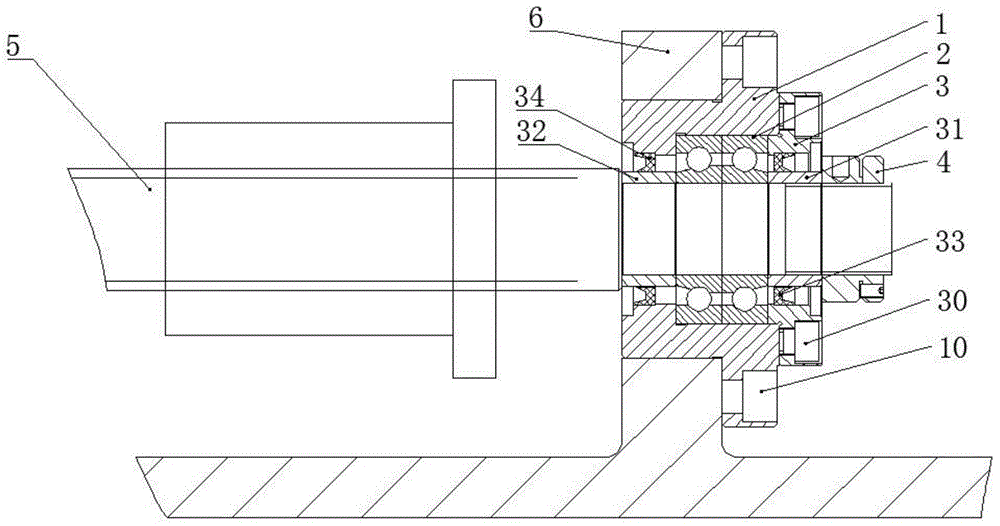
[0026] figure 1 An implementation form according to the present invention is shown, which includes:

[0027] Screw rod 5, which is a cylindrical rod-shaped structure, the end of the screw rod 5 is provided with a shaft shoulder, and the shaft shoulder is provided with a threaded portion;

[0028] The flanged bearing sleeve 1 is a combined structure of a cylinder and a flange. The flanged bearing sleeve 1 has a stepped through hole inside, and the stepped through hole is composed of a large and a small round hole. The large and small round holes are coaxially connected, the larg...


PUM


Abstract

The invention discloses an integral bearing mechanism for a ball screw. The integral bearing mechanism comprises a screw, a flange-type bearing sleeve, a bearing group, a gland and a locking nut, wherein the end part of the screw is provided with a shaft shoulder, and the shaft shoulder is provided with a threaded part; a step-type through hole is formed inside the flange-type bearing sleeve, the step-type through hole consists of a large circular hole and a small circular hole, and the large circular hole and the small circular hole are coaxially arranged; the bearing group consists of at least two bearings of the same model number, and the bearing group is installed in the large circular hole; the gland is of a disc-shaped structure, a shaft through hole is formed in the circular hole, a cylindrical lug boss is arranged on one end of the gland, the lug boss is installed into the large circular hole and fit to the outer end surface of the bearing group; the locking nut is matched with the threaded part of the screw; the inner end surface of the bearing group is fit to a stepped surface formed by the large circular hole and the small circular hole, and the inner end surface of the locking nut is fit to the outer end surface of the gland. By adopting the integral bearing mechanism, the contact rigidity and high-precision stable rotation property of the bearing can be greatly improved; moreover, the positioning precision stability is good.

Description

technical field [0001] The invention relates to a screw rod support device, in particular to an integral bearing mechanism for a ball screw rod. Background technique [0002] The ball screw pair is a mechanical element composed of screw, nut, ball and other parts. It is a screw transmission element with balls as the rolling body between the screw and the nut. The ball screw pair is the most commonly used transmission element on precision machine tools. It is an ideal product for converting the rotary motion of the screw into the linear motion of the nut, or converting the linear motion of the nut into the rotary motion of the screw. At the same time, it has high Characterized by precision, reversibility and high efficiency. [0003] In order to obtain high transmission accuracy for the feed system of precision machine tools, in addition to the rigidity requirements of the ball screw itself, the correct installation and support mechanism of the ball screw should not be under...

Claims


Application Information

Patent Timeline
IPC IPC(8): B23Q5/40B23Q5/56
CPCB23Q5/404B23Q5/56
Inventor 王立民袁旎呼如亮朱云云吴亚辉
Owner JIANGSU YUANLI AVIA PRECISION MACHINE TOOL
Learn More