
Anti-backlash mechanism

A technology of eliminating backlash and adjusting mechanism, applied in the field of transmission, can solve the problems of increasing the cost of gear processing, and achieve the effect of improving the transmission accuracy and simplifying the adjustment process.

Pending Publication Date: 2022-05-17
大公数控(北京)科技有限公司
View PDF0 Cites 0 Cited by
  • Summary
  • Abstract
  • Description
  • Claims
  • Application Information

AI Technical Summary

Problems solved by technology

[0004] In the existing technology, the way of improving the machining accuracy of gears is usually used to reduce the meshing clearance as much as possible. However, this way brings a significant increase in the cost of gear machining

Method used


Image

  • Anti-backlash mechanism
  • Anti-backlash mechanism
  • Anti-backlash mechanism

Examples


Embodiment Construction

[0042] In order to make the purpose, technical solutions and advantages of the embodiments of the present invention more clear, the technical solutions of the embodiments of the present invention will be clearly and completely described below in conjunction with the drawings of the embodiments of the present invention. Apparently, the described embodiments are some, not all, embodiments of the present invention. Based on the described embodiments of the present invention, all other embodiments obtained by persons of ordinary skill in the art without creative efforts shall fall within the protection scope of the present invention.

[0043] Unless otherwise defined, the technical terms or scientific terms used in the present invention shall have the usual meanings understood by those skilled in the art to which the present invention belongs. "First", "second" and similar words used in the present invention do not indicate any order, quantity or importance, but are only used to d...


PUM


Abstract

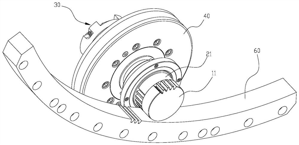
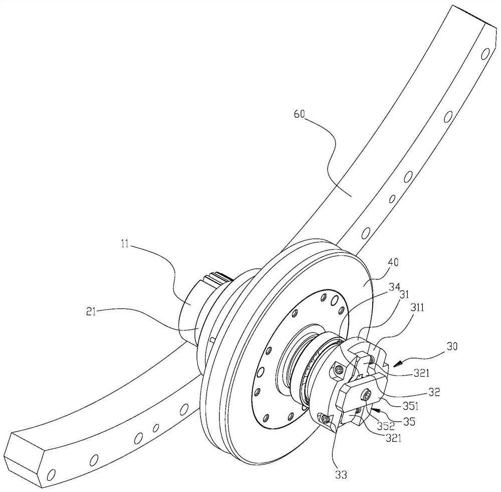
The invention discloses an anti-backlash mechanism which comprises a mandrel component, a first gear and a second gear. The shaft sleeve component is arranged outside the core shaft component in a sleeving mode, a second gear is formed on the head portion of the shaft sleeve component, the first gear and the second gear are coaxial and arranged side by side front and back, and the first gear and the second gear are both used for being meshed with tooth components of external equipment at the same time; the shaft sleeve component is sleeved with the driven component, and the driven component and the shaft sleeve component coaxially rotate; the adjusting mechanism is arranged at the tail of the mandrel component and the tail of the shaft sleeve component, and the adjusting mechanism adjusts the dislocation amount between the outer teeth of the first gear and the outer teeth of the second gear by changing the relative rotation angle of the mandrel component and the shaft sleeve component.

Description

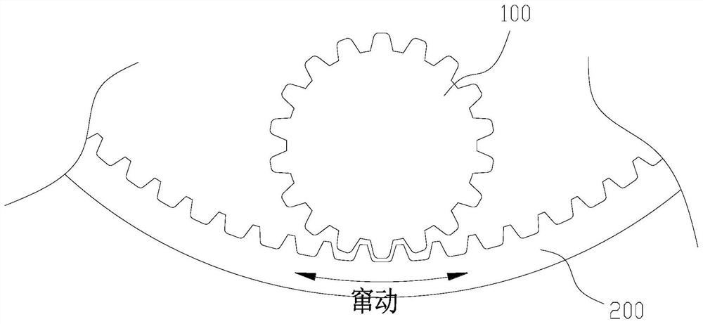
technical field [0001] The invention relates to the technical field of transmission, in particular to an anti-backlash mechanism for gear transmission. Background technique [0002] It is known that two gears can transmit rotary motion and power through meshing, such as figure 1 said, the figure 1 It shows the state when the gear meshes with the inner teeth of the ring gear. It can be seen from the figure that there is a meshing gap between the outer teeth of the gear and the inner teeth of the ring gear. Most of the meshing gaps are caused by machining errors and other principles. . Under lower transmission accuracy requirements, the meshing gap is allowed to exist, however, under higher transmission accuracy requirements, the meshing gap will cause the following problems: [0003] After one gear is braked, the other gear meshing with this gear can still produce a large amount of circumferential movement. [0004] In the prior art, the method of improving the machining ...

Claims


Application Information

Patent Timeline
Patent Type & Authority Applications(China)
IPC IPC(8): F16H57/12
CPCF16H57/12F16H2057/125
Inventor 韩庆元谢文洪齐波刘思远陈小明
Owner 大公数控(北京)科技有限公司
Learn More