Construction and implementation method of a tool-type anchorage end of a cantilevered external scaffold steel beam

A technology for external scaffolding and anchoring ends, which is applied to the accessories of scaffolding, scaffolding supported by house structures, building structures, etc., which can solve problems such as slow construction speed, low safety, and waste of steel, so as to improve construction speed and safety. , Fast installation effect

Active Publication Date: 2017-04-05
JIANGSU NANTONG SANJIAN CONSTRUCTION GROUP CO LTD
View PDF6 Cites 1 Cited by
  • Summary
  • Abstract
  • Description
  • Claims
  • Application Information

AI Technical Summary

Problems solved by technology

[0003] There are various disadvantages in the above three methods. As far as the first method is concerned, the pre-embedded length of the U-bolt used at the anchorage end must meet the anchorage length requirements. Since the pre-embedded floor concrete cannot be taken out, it is a one-time use. There are a large number of shaped steel beams, which results in a waste of steel; in the second method, the bolts and steel backing plates can be taken out and reused, but the welding quality of the bolts and steel backing plates directly affects the quality of the fixed end of the shaped steel cantilever beam. Anchoring effect, because the bolts and the lower steel backing plate are connected by surrounding welding, its safety is low; as for the third method, since the U-shaped bolts have to pass through the floor, and there is a steel backing plate under it, so there is no The standard formwork suitable for the whole width needs to be supported separately by special-shaped formwork, and the lower support of the special-shaped formwork and other parts of the formwork support cannot be integrated, resulting in slow construction speed and waste of formwork

Method used


Image

  • Construction and implementation method of a tool-type anchorage end of a cantilevered external scaffold steel beam
  • Construction and implementation method of a tool-type anchorage end of a cantilevered external scaffold steel beam
  • Construction and implementation method of a tool-type anchorage end of a cantilevered external scaffold steel beam

Examples


Embodiment Construction

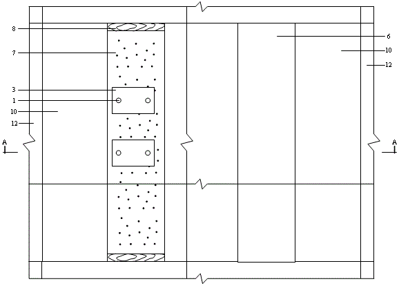
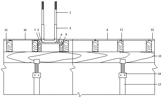
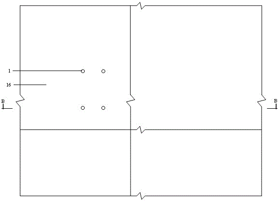
[0025] Depend on Figure 1-8 It can be seen that the structure of the tool-type anchorage end of a kind of cantilevered external scaffold steel beam includes a scaffold support with an adjustable support head 14 on the top of the φ48 steel pipe 15, a standard main keel 13 placed on the scaffold support, and a standard main keel. The standard sub-keel 11 placed above the keel along its vertical direction, the standard small formwork 10 for carrying the floor concrete 16 at the upper end of the standard sub-keel, the joint formwork 6 and the standard formwork 12, the PVC casing 2 passing through the concrete, and the steel backing plate 3 U-bolts 1 with PVC sleeves, steel beams 17 placed between the U-bolts, joint templates for bearing cement mortar 7 placed on non-standard sub-keels 9 under the steel beams, vertical Blocking wooden squares 8 respectively placed at both ends of the joint formwork, and steel pressure plates 4 pressed on the steel beams and fixed by nuts 5 .

[0...


PUM


Abstract

The invention relates to a construction and implementation method for a tool type anchoring end of overhung external scaffold profile steel beams. A scaffold support, a main standard keel, auxiliary standard keels, small standard formworks, seam splicing formworks, standard formworks, PVC sleeve pipes, U-shaped bolts, profile steel beams, seam splicing formworks, plugging battens and heating steel plates are included, wherein the scaffold support is built through phi 48 steel tubes, adjustable supporting heads are arranged on the top of the scaffold support, the main standard keel is arranged on the scaffold support in the full length, the auxiliary standard keels are arranged on the main standard keel in the perpendicular direction of the main standard keel, the small standard formworks, the seam splicing formworks and the standard formworks are arranged at the upper end of the auxiliary standard keels and used for carrying floor slab concrete, the PVC sleeve pipes penetrate through the concrete, the U-shaped bolts penetrate into steel cushion plates and are sleeved with the PVC sleeve pipes, the seam splicing formworks are arranged below the profile steel beams and on auxiliary non-standard keels and used for carrying cement mortar, the plugging battens are arranged perpendicular to the two ends of the seam splicing formworks in the length direction, and the heating steel press plates press the profile steel beams and are fixed through nuts. The safety of the profile steel beam anchoring end can be effectively improved, the U-shaped bolts, the steel cushion plates, the formworks, the auxiliary non-standard keels and the battens can be tooled and used repeatedly, the material cost is greatly lowered, hard blocks formed by the cement mortar can be scraped and then used for rod padding, the installation speed is high, and the construction speed is increased.

Description

technical field [0001] The invention relates to the field of building construction, in particular to a construction and implementation method of a tool-type anchoring end of a cantilevered external scaffold steel beam. Background technique [0002] The cantilevered external scaffold is widely used in construction because of its small material occupation and fast turnover of turnover materials, and the key component supporting the cantilevered external scaffold is a steel beam. Due to the tight construction schedule, the shaped steel beams will be installed after the concrete pouring is completed, and the formwork and support system of the floor slab will not be removed until a week later. Therefore, there are three current methods for fixing the anchored ends of the shaped steel beams on the floor concrete: one The method is to pre-embed U-shaped bolts in the floor concrete, pour the floor concrete, and then fix the steel beams on the pre-embedded U-shaped bolts through stee...

Claims


Application Information

Patent Timeline
IPC IPC(8): E04G5/04E04G3/18
Inventor 魏勇金振宇陆建兵许芬杜勇汤生陈杨施卫德黄正杰施华平
Owner JIANGSU NANTONG SANJIAN CONSTRUCTION GROUP CO LTD
Why Eureka
Try Eureka