Pusher lubricating device

A lubricating device and pusher technology, which is applied in the direction of engine lubrication, lubricating parts, engine components, etc., can solve problems such as easy to absorb dust and affect the movement of the device, and achieve powerful functions, simple structure, and avoid unsmooth movement of the device Effect

Active Publication Date: 2015-05-06
ANHUI XINHONG GENERAL EQUIP MFG
View PDF9 Cites 0 Cited by
  • Summary
  • Abstract
  • Description
  • Claims
  • Application Information

AI Technical Summary

Problems solved by technology

[0003] The technical problem to be solved by the present invention is to provide a thruster lubricating device to solve the problem that the existing lubricating method is easy to absorb dust and affect the movement of the device

Method used


Image

  • Pusher lubricating device
  • Pusher lubricating device
  • Pusher lubricating device

Examples


Embodiment Construction

[0025] In the following, numerous specific details are set forth in order to provide a thorough understanding of the concepts underlying the described embodiments. It will be apparent, however, to one skilled in the art that the described embodiments may be practiced without some or all of these specific details. In other instances, well known processing steps have not been described in detail.

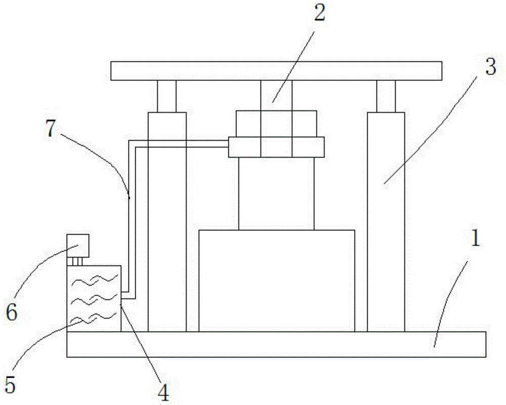
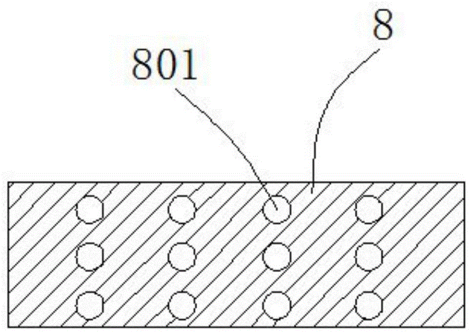
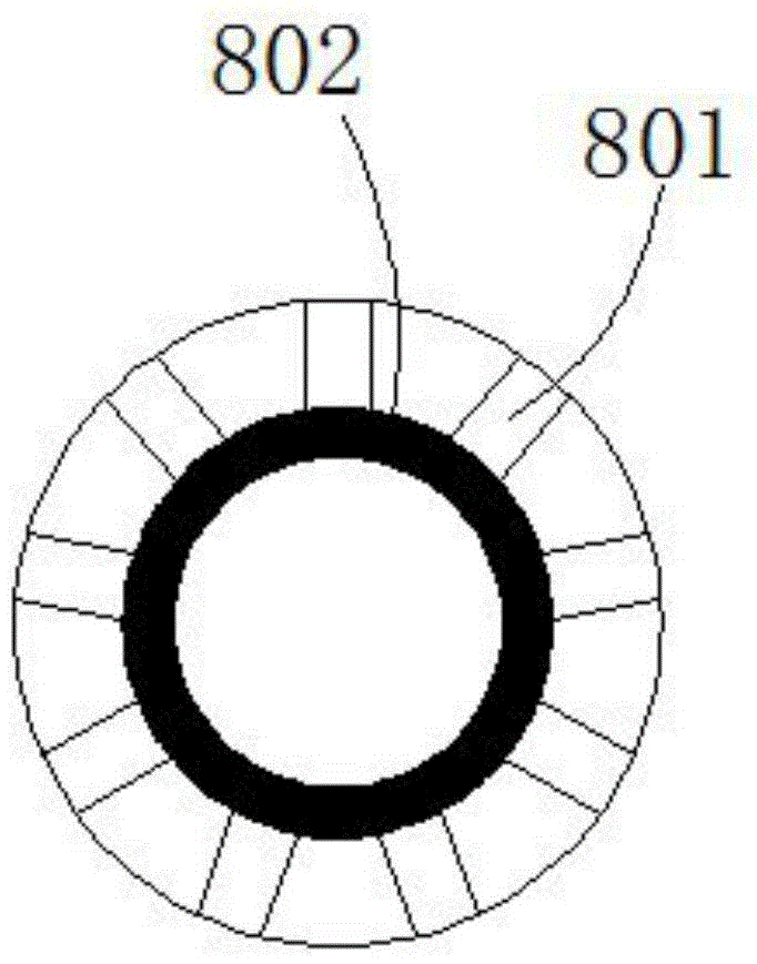
[0026] like figure 1 , figure 2 , image 3 , Figure 4 As shown, it includes a pusher base plate 1, a guide rod 2, and a push rod 3, including a lubricating box 4, lubricating oil 5, a pressurizing pump 6, an oil delivery pipe 7, and a lubricating ring 8. The described lubricating box 4 is located on the left side of the pusher base plate 1. side top, the lubricating box 4 is threadedly connected with the pusher bottom plate 1, the pressure pump 6 is located at the top of the lubricating box 4, the pressurized pump 6 is threadedly connected with the lubricating box 4, and the oil...


PUM


Abstract

The invention discloses a pusher lubricating device. The pusher lubricating device comprises a pusher bottom board, a guiding rod, pushing rods, a lubricating tank, lubricating oil, a pressuring pump, an oil conveying pipe and a lubricating ring. Compared with the prior art, the lubricating device has the advantages that the lubricating oil in the lubricating tank is conveyed to the internal wall of the lubricating ring through the oil conveying pipe by the pressuring pump and then is conveyed to the pushing rods through the lubricating ring, so that the lubricating oil lubricates the guiding rod; the device is simple in structure and powerful in function, and the problem that the movement of the device is unsmooth due to dust is solved.

Description

technical field [0001] The invention relates to a lubricating device, in particular to a lubricating device for a pusher. Background technique [0002] Pushers are widely used in the industrial field, but the traditional lubrication of pushers is to spray oil on the outer wall of the push rod, so that the lubricating oil is exposed to the air, and the dust absorbed in this way is easy to make the work of the push rod not smooth. In view of the above defects, it is necessary to Design a thruster lubrication device. Contents of the invention [0003] The technical problem to be solved by the present invention is to provide a thruster lubricating device to solve the problem that the existing lubricating method is easy to absorb dust and affect the movement of the device. [0004] In order to solve the above technical problems, the technical solution of the present invention is: a pusher lubricating device, including a pusher bottom plate, a guide rod, a push rod, including a...

Claims


Application Information

Patent Timeline
Patent Type & Authority Applications(China)
IPC IPC(8): F16N7/38F16N21/00F16N33/00
Inventor 周正祥韩宏超韩玮
Owner ANHUI XINHONG GENERAL EQUIP MFG
Why Eureka
Try Eureka